Magnetron

a magnet and tungsten technology, applied in the field of magnets, can solve the problems of reducing the oscillation efficiency of the magnetron, causing the stop of the oscillation of the magnetron, and the inside vacuum degree, so as to reduce the noise, reduce the noise, and reduce the quantity of thorium tungsten use

Inactive Publication Date: 2008-05-01
PANASONIC CORP
View PDF4 Cites 5 Cited by
  • Summary
  • Abstract
  • Description
  • Claims
  • Application Information

AI Technical Summary

Benefits of technology

[0017] According to a magnetron as set forth in the above item (1), since the portion of the upper end hat in contact with one end portion of the filament coil is held not in contact with the center lead, heat generated in the filament coil can travel to the upper end hat without traveling directly to the center lead. Therefore, for example, even when the quantity of the input power is reduced to such a degree as to be able to reduce noise, or even when the electron radiation area of the filament coil is reduced whereby the quantity of heat radiated from the filament coil is reduced, the heat radiated from the filament coil can be supplied to the upper end hand with good efficiency, thereby being able to display the getter effect fully. Also, when the electron radiation area of the filament coil is reduced, the quantity of use of thorium tungsten, which is the main material of the filament coil, can be reduced, which makes it possible to lower the product price of the magnetron. Thus, according to the above-mentioned structure, while maintaining the getter effect to keep a good degree of vacuum, noise reduction and cost reduction can be realized.
[0018] According to a magnetron as set forth in the above item (2), since the portion of the upper end hat in contact with the filament coil is formed small, the portion of the upper end hat in contact with the filament coil can be kept not in contact with the center lead. Also, simply by adding a step of reducing the thickness of the above portion of the upper end hat to the conventional upper end hat manufacturing step, the present portion can be made not in contact with the center lead. Also, the quantity of use of molybdenum, which is the main material of the end hat, can be reduced to thereby be able to lower the product price of the magnetron.
[0019] Also, since a microwave using apparatus according to the invention includes a magnetron as set forth in the above item (1) or (2), in the present microwave using apparatus, not only noise reduction can be attained but also the product cost can be reduced.

Problems solved by technology

As known well, when a magnetron is operated, there is emitted a gas from the composing members of the magnetron and, due to the gas, the degree of vacuum of the inside of the magnetron is lowered and the oscillation efficiency of the magnetron is thereby lowered, which can raise a fear that the oscillation of the magnetron is caused stop.

Method used


Image

  • Magnetron
  • Magnetron
  • Magnetron

Examples


Embodiment Construction

[0026] Now, description will be given below in detail of a preferred mode for enforcing the invention with reference to the accompanying drawings.

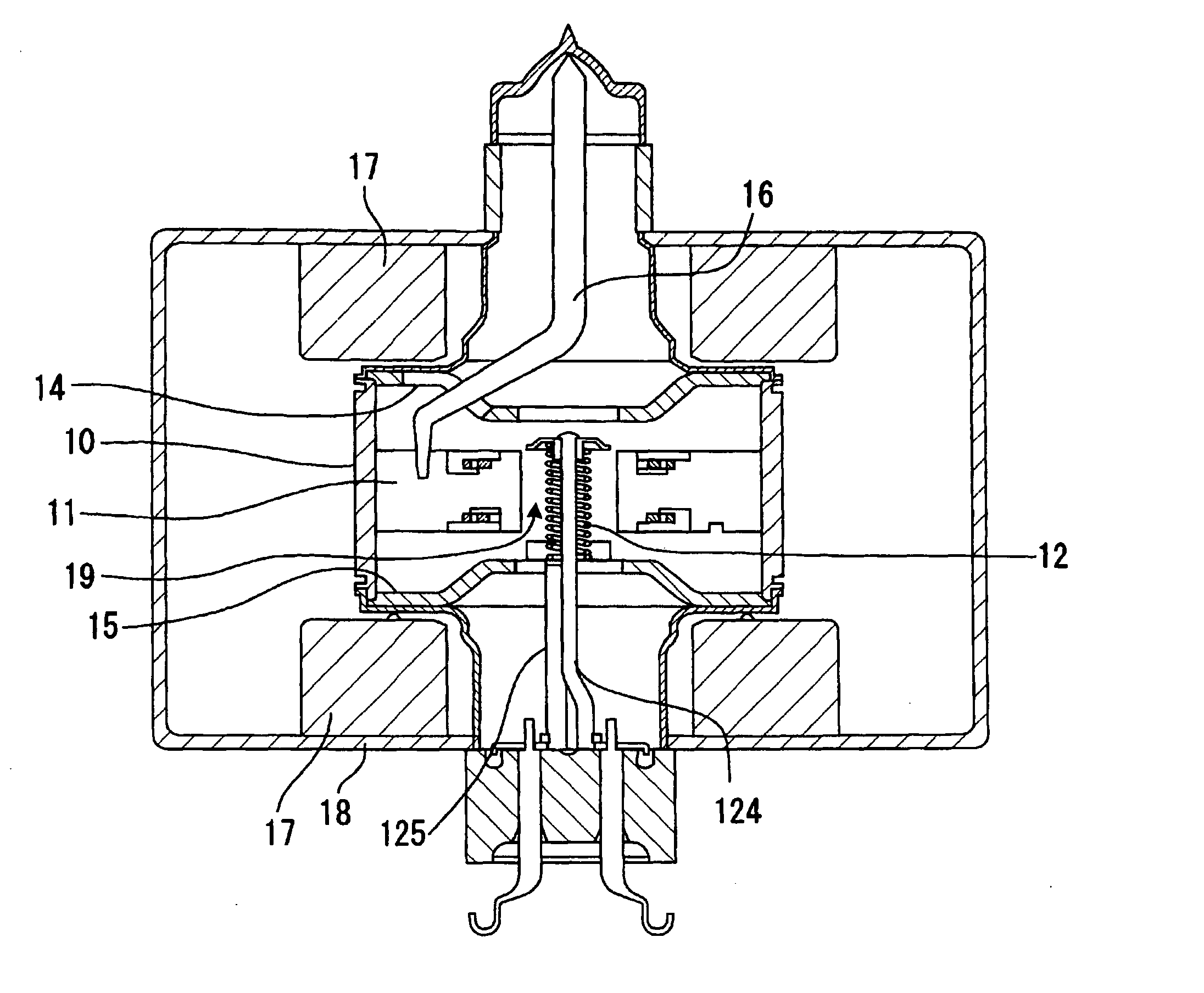
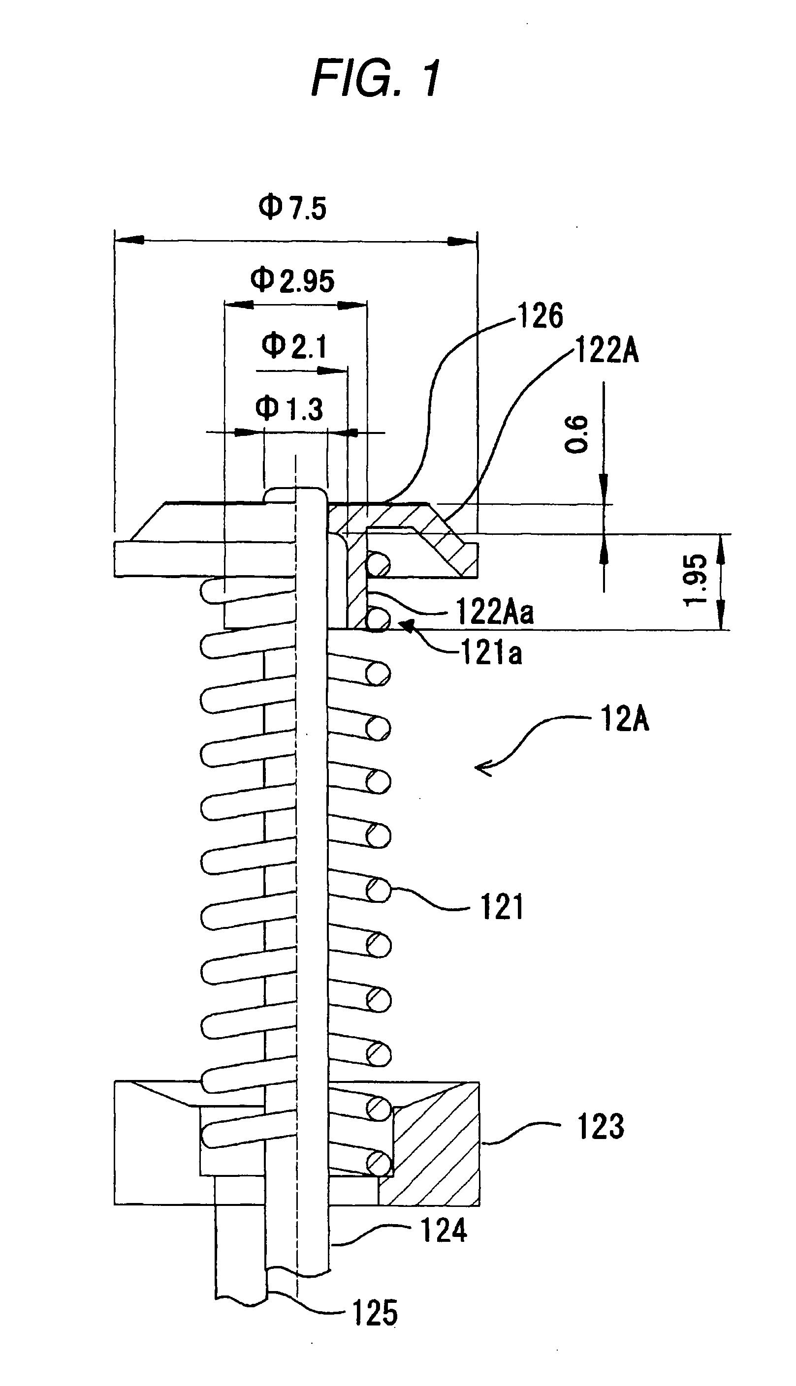
[0027]FIG. 1 is a partial section view of a cathode structure member used in a magnetron according to an embodiment of the invention. In FIG. 1, parts used in common with those of the cathode structure member 12 shown in the above-mentioned FIG. 6 are given the same designations. Also, a magnetron according to the present embodiment is similar in structure to the magnetron shown in FIG. 5 except for the cathode structure member and thus, when the need arises for the sake of explanation, FIG. 5 will be quoted.

[0028] In FIG. 1, a magnetron according to the present embodiment includes a cathode structure member 12A which, even when the quantity of input power is reduced to such a degree as to be able to reduce noise, or even when the electron radiation area of a filament coil 121 is reduced, can provide the temperature that allows a getter ...


PUM


Abstract

In the magnetron, an upper end hat 122A is used as a composing element of a cathode structure member 12A and includes a portion 122Aa which is in contact with one end portion 121a of a filament coil 121. The thickness of the portion 122Aa is reduced, whereby the portion 122Aa is held not in contact with a center lead 124. Owing to this, heat generated in the filament coil 121 can travel to the upper end hat 122A without traveling directly to the center lead 124. Therefore, even when the quantity of input power is reduced to such a degree as to be able to reduce noise, or even when the electron radiation area of the filament coil 121 is reduced, the getter effect can be displayed fully. As a result of this, noise reduction and cost reduction can be realized at the same time.

Description

BACKGROUND OF THE INVENTION [0001] 1. Field of the Invention [0002] The present invention relates to a magnetron for use in a microwave using apparatus such as a microwave oven. [0003] 2. Description of the Related Art [0004] Conventionally, there is proposed a technology which uses a getter for the purpose of enhancing the degree of vacuum in the inside of a magnetron (for example, see the patent reference 1). FIG. 5 is a longitudinal section view of a magnetron for use in a conventionally general microwave oven. In FIG. 5, in the inside of a cylindrical-shaped anode barrel member 10, there are radially arranged anode vanes 11; and, there are provided cavity resonators formed of spaces respectively enclosed by the mutually adjoining anode vanes 11 and anode barrel member 10. In the central portion of the anode barrel member 10, there is provided a cathode structure member 12; and, a space enclosed by the cathode structure body 12 and anode vanes 11 provides an action space 19. [000...

Claims


Application Information

Patent Timeline
Patent Type & Authority Applications(United States)
IPC IPC(8): H01J25/50
CPCH01J25/587H01J23/05
Inventor KUWAHARA, NAGISAISHII, TAKESHIAIGA, MASAYUKI
Owner PANASONIC CORP
Why Eureka
Try Eureka