Apparatus for moving curved-surface mirror, exposure apparatus and device manufacturing method

a technology of curved surfaces and mirrors, applied in the direction of mountings, printing, instruments, etc., can solve the problems of optical characteristics that may worsen, and optical characteristics may worsen

Inactive Publication Date: 2008-05-01
CANON KK
View PDF6 Cites 13 Cited by
  • Summary
  • Abstract
  • Description
  • Claims
  • Application Information

AI Technical Summary

Benefits of technology

[0009]The present invention has been made in light of the foregoing background. It is an object of the present invention, for example, to precisely adjust the position of a curved surface mirror.

Problems solved by technology

However, unless other components and displacement error can be sufficiently suppressed with respect to drive in a desired direction and drive displacement, optical characteristics will worsen instead.
Further, if the rigidity of the mechanism declines owing to an increase in degrees of freedom of drive, positional deviation may increase owing to disturbances even if it is possible to adjust drive to the desired position, and optical characteristics may worsen.

Method used


Image

  • Apparatus for moving curved-surface mirror, exposure apparatus and device manufacturing method
  • Apparatus for moving curved-surface mirror, exposure apparatus and device manufacturing method
  • Apparatus for moving curved-surface mirror, exposure apparatus and device manufacturing method

Examples


embodiment 1

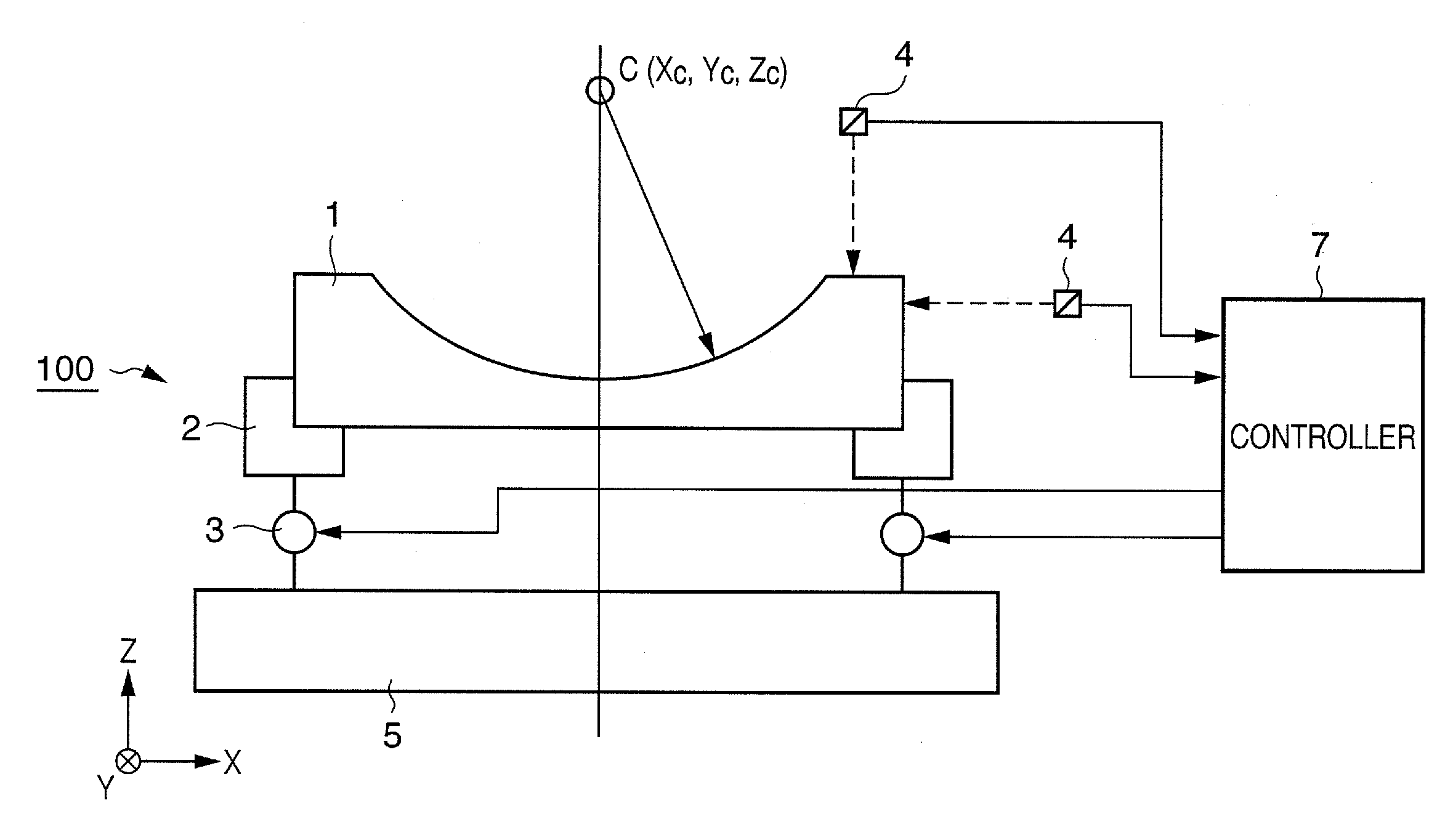
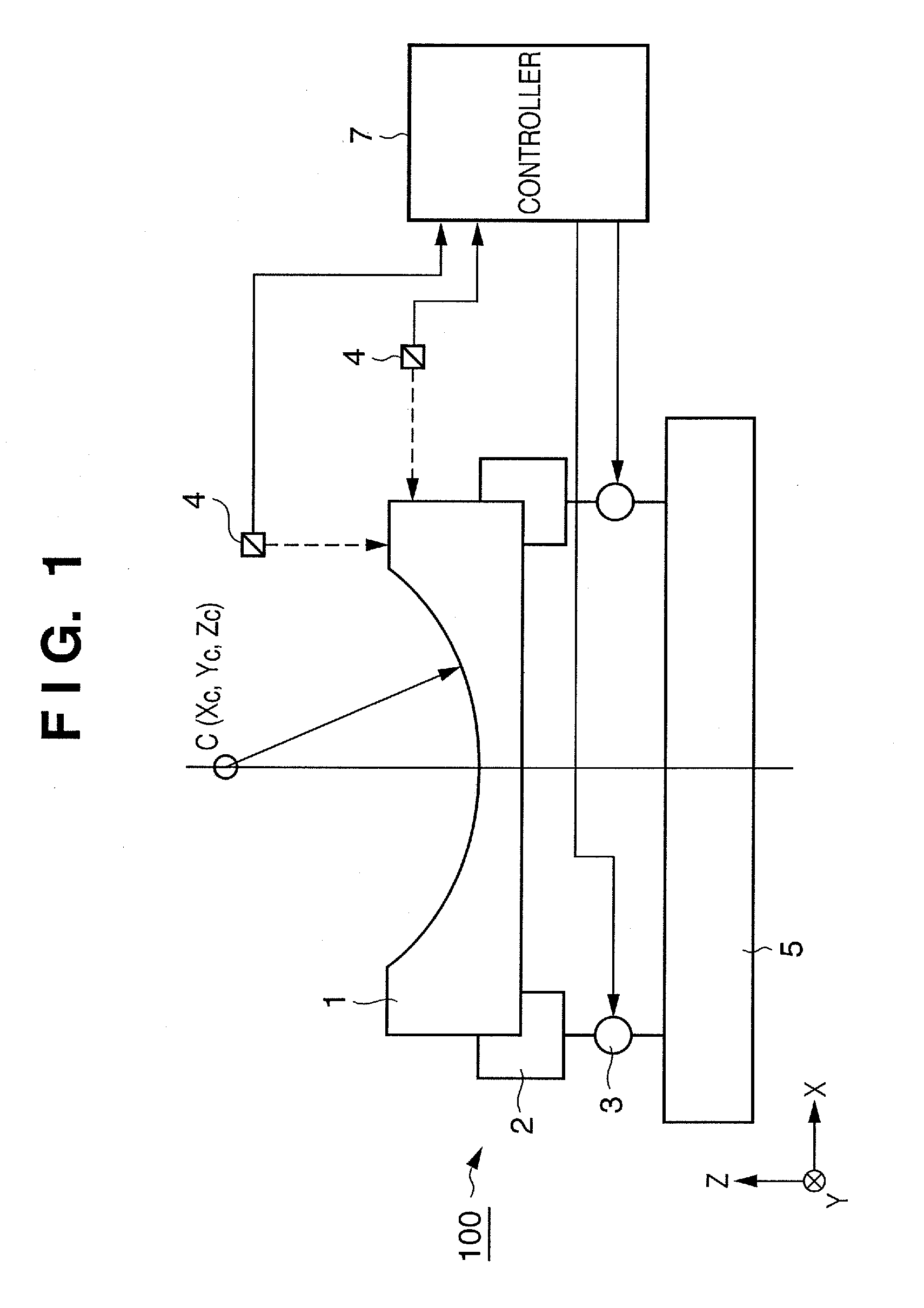
[0020]FIG. 1 is a diagram illustrating the structure of an optical element driving apparatus 100 according to this embodiment. As shown in FIG. 1, a curved-surface mirror 1, which serves as an optical element, has a curved reflective surface. A typical example of a mirror used as the curved-surface mirror 1 is a spherical mirror having a reflective surface that defines a spherically concave surface. Let the direction of the optic axis be the Z axis, let two other directions forming a rectangular coordinate system with this axis be X and Y axes, and let the six-degree-of-freedom of the curved-surface mirror 1 be translations X, Y, Z and rotations θx, θy, θz, respectively, about these axes. Further, let C be the center of curvature of the curved-surface mirror 1, and let C(Xc,Yc,Zc) represent the coordinates of the center of curvature. Further, let (ΔXc, ΔYc, ΔZc) represent a change in this position.

[0021]A mirror support plate 2 supports the curved-surface mirror 1. Three or more act...

second embodiment

[0034]The X, Y, Z directions may be the three-degree-of freedom for driving an optical element driving apparatus for performing an adjustment in such a manner that the position C(Xc,Yc,Zc) of the center of curvature of the curved-surface mirror 1 takes on a desired value.

[0035]In this case, in a manner similar to the first embodiment, the controller 7 calculates fluctuation (ΔXm, ΔYm, ΔZm, Δθxm, Δθym, Δθzm) in position and attitude of the curved-surface mirror 1 through six-degree-of-freedom by a coordinate transformation based upon the values measured by the position sensors 4 that measure six or more points on the curved-surface mirror 1. Next, the controller 7 calculates fluctuation (ΔXc, ΔYc, ΔZc) in the position C of the center of curvature of curved-surface mirror 1 by a coordinate transformation from the position and attitude of the curved-surface mirror 1 through six-degree-of-freedom. It should be noted that the fluctuation in the position C of the center of curvature may b...

third embodiment

[0038]The Z, X directions and rotation θx about the X axis may be the three-degree-of-freedom for driving an optical element driving apparatus for performing an adjustment in such a manner that the position C(Xc,Yc,Zc) of the center of curvature of the curved-surface mirror 1 takes on a desired value.

[0039]Let (ΔXc, ΔYc, ΔZc) represent the positional deviation or other driving components of the center of curvature calculated by a coordinate transformation of the values measured by the position sensors 4. In this embodiment, the actuators 3 are driven and controlled so as to compensate for fluctuation of the position C of the center of curvature by an X translation of ΔXc and rotation θx of ΔYc about the X axis. Further, the actuators 3 are driven and controlled so as to compensate for fluctuation of the position C of the center of curvature by a Z translation with regard to ΔZc.


PUM


Abstract

An apparatus for moving a curved-surface mirror is provided. The apparatus includes at least three actuators configured to move the curved-surface mirror, at least five position sensors configured to sense the position of the curved-surface mirror, and a controller configured to calculate coordinates of a center of curvature of the curved-surface mirror with three-degree-of-freedom based on positions sensed by the at least five position sensors, and to control driving of the at least three actuators in accordance with a difference between the calculated coordinates and predetermined coordinates.

Description

BACKGROUND OF THE INVENTION[0001]1. Field of the Invention[0002]The present invention relates to an apparatus for moving a curved-surface mirror.[0003]2. Description of the Related Art[0004]An exposure apparatus is used in a photolithographic process for the manufacture of a semiconductor element to expose the circuit pattern of a reticle and transfer it to a silicon wafer, by way of example. Owing to demand for higher integration of semiconductor elements, step-and-scan exposure systems now dominate and have supplanted the conventional step-and-repeat exposure systems. A step-and-scan exposure apparatus is a scanning exposure apparatus in which slit-shaped illuminating light is partially emitted from one end of a reticle and the entirety of a circuit pattern is exposed on a wafer (substrate) via a projection optical system while a reticle stage holding the reticle and a wafer stage holding the wafer are driven synchronously.[0005]In an exposure apparatus of this kind, the resolutio...

Claims


Application Information

Patent Timeline
Patent Type & Authority Applications(United States)
IPC IPC(8): G02B26/08
CPCG02B7/1827G03F7/70825G03F7/70266G02B26/0825
Inventor ASADA, KATSUMI
Owner CANON KK
Why Eureka
Try Eureka