
Dc-dc converter with integrated transformer assembly composed of transformer pair

a transformer assembly and converter technology, applied in the direction of electric variable regulation, process and machine control, instruments, etc., can solve the problems of increased cost of manufacturing a and the difficulty of use, so as to reduce the number of components of the dc to dc converter with the common magnetic path structure.

Inactive Publication Date: 2008-05-01
DENSO CORP +1
View PDF12 Cites 27 Cited by
  • Summary
  • Abstract
  • Description
  • Claims
  • Application Information

AI Technical Summary

Benefits of technology

[0012] For this reason, the number of components of the DC to DC converter with the common magnetic-path structure can be reduced.
[0013] In addition, the orientations of the first and second magnetic fluxes φ1 and φ2 are determined to reduce the upper limit of the total magnetic flux, making it possible to reduce, in total size and weight, the DC to DC converter with the common magnetic-path structure as compared with DC to DC converters with a pair of separated transformers.
[0015] In view of the circumstances set forth above, an object of at least one aspect of the present invention is to provide DC to DC converters with an integrated transformer assembly composed of a pair of first and second transformers, which allow reduction in size and / or weight of the integrated transformer assembly while maintaining the cost of manufacturing it.

Problems solved by technology

However, the integral core of a DC to DC converter with the common-magnetic path structure may have a specific structure, which may make it difficult to use, as the integral core, a general-purpose core for normal transformers in order to manufacture a DC to DC converter with the common-magnetic path structure.
This may cause the cost of manufacturing a DC to DC converter with the common-magnetic path structure to increase.

Method used


Image

  • Dc-dc converter with integrated transformer assembly composed of transformer pair
  • Dc-dc converter with integrated transformer assembly composed of transformer pair
  • Dc-dc converter with integrated transformer assembly composed of transformer pair

Examples


Embodiment Construction

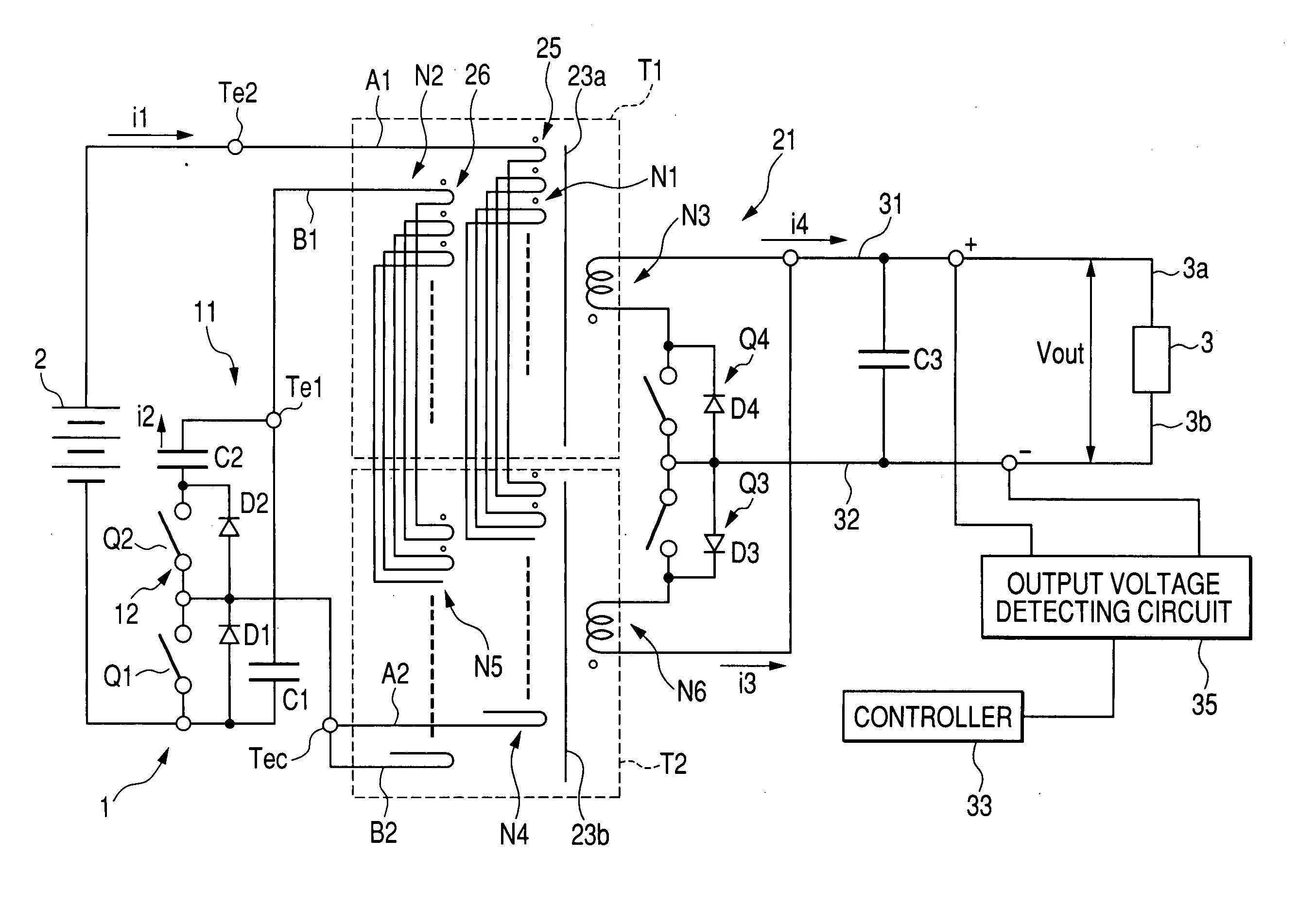
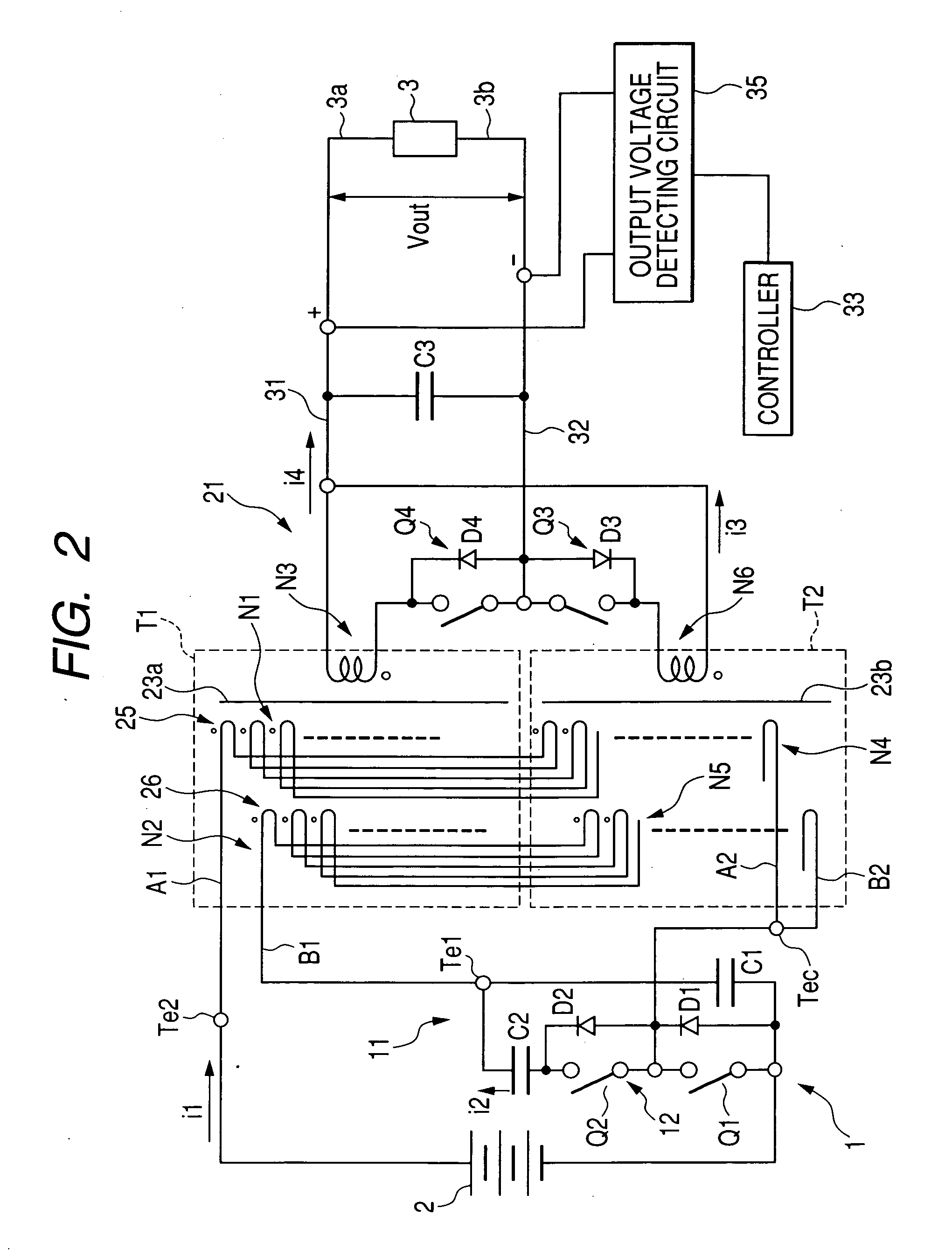
[0054] An embodiment of DC to DC converters according to the present invention will be described hereinafter with reference to the accompanying drawings.

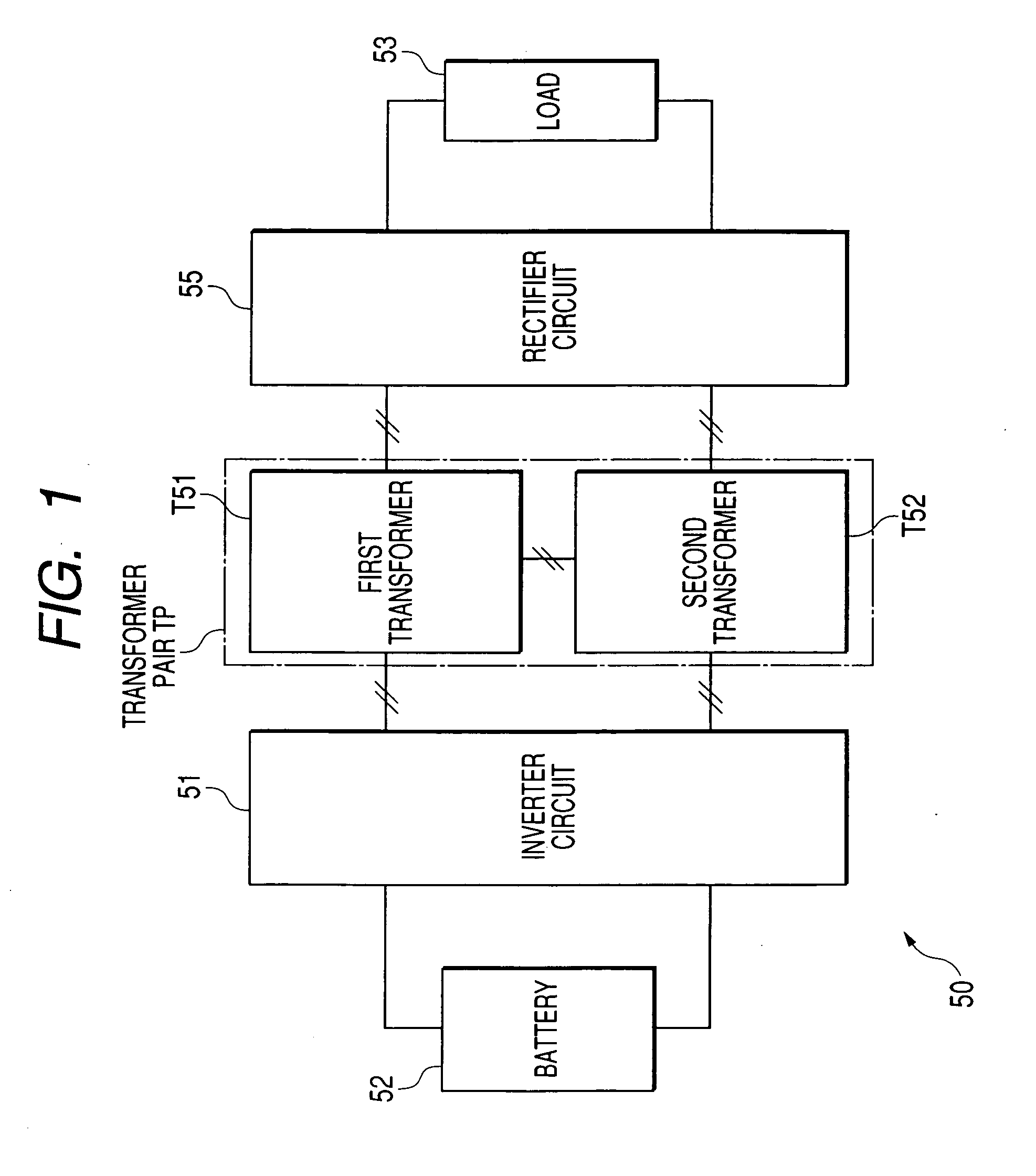
[0055] A skeleton structure of a DC to DC converter 50 with a pair of first and second transformers and operations thereof according to the embodiment of the present invention will be described in accordance with FIG. 1.

[0056] The DC to DC converter 50 serves as a unidirectional step up / down converter, the input side of which is coupled to an input DC power source (battery) 52. The output side of the DC to DC converter 100 is coupled to a load 53.

[0057] The DC to DC converter 50 includes a transformer pair TP that consists of a pair of first and second transformers (transformer assemblies) T51 and T52. The DC to DC converter 50 also includes an inverter circuit 51 and a rectifier circuit 55.

[0058] The inverter circuit 51 is arranged between the input DC power source 52 and the first and second transformers T51 and T52. The recti...


PUM


Abstract

In an integrated transformer assembly, a common coil member has a first portion alternately wound, for each one electromagnetic turn, around the first core member and around the second core member. The first portion of the common primary coil member wound around the first core member is magnetically linked to the first magnetic path thereof so as to constitute a first primary coil. The first portion of the common primary coil member wound around the second core member is magnetically linked to the second magnetic path thereof so as to constitute a second primary coil. The first and second primary coils are connected in series. A secondary coil member has first and second secondary coils. The first and second secondary coils are arranged to be magnetically linked to the first and second primary coils of the common primary coil member, respectively.

Description

CROSS REFERENCE TO RELATED APPLICATION [0001] This application is based upon and claims the benefit of priority of the prior Japanese Patent Application 2006-296539 filed on Oct. 31, 2006 so that the contents of which are incorporated herein by reference. FIELD OF THE INVENTION [0002] The present invention relates to DC (direct current) to DC converters with an integrated transformer assembly composed of a transformer pair. BACKGROUND OF THE INVENTION [0003] DC to DC converters with a transformer are configured to completely isolate between input and output thereof, and therefore, they have been widely used. [0004] In such DC to DC converters, DC to DC converters with a pair of transformers have been well-known, some of which are disclosed in U.S. Pat. No. 7,254,046 B2 corresponding to Japanese Unexamined Patent Publications No. 2005-51994 and No. 2005-51995. [0005] In the US patent Publication, one type of DC to DC converters is provided with a first converting circuit between an i...

Claims


Application Information

Patent Timeline
IPC IPC(8): H02M3/335H01F5/00
CPCH01F17/043H01F27/255H01F30/04H02M7/003H01F30/12H02M3/33569H01F30/06H02M3/33571H02M3/01
Inventor KAWASAKI, KOJIYAMASHITA, TSUYOSHI
Owner DENSO CORP
Learn More