Method and Apparatus for Characterizing Modulation Schemes in an HFC Network

a modulation scheme and network technology, applied in data switching networks, frequency-division multiplexes, instruments, etc., can solve the problem of determining the highest modulation complexity that may be supported, and achieve the effects of avoiding affecting active services, maximizing network resources, and improving signal quality and network speed

Inactive Publication Date: 2008-05-01
GOOGLE TECH HLDG LLC
View PDF61 Cites 37 Cited by
  • Summary
  • Abstract
  • Description
  • Claims
  • Application Information

AI Technical Summary

Benefits of technology

[0011]The invention enables the technician or engineer to remotely characterize the modulation schemes which are available to a network without significant phase noise or narrowband interference at a central location, such as the headened, such as by using the Motorola BSR64000, rather than using external test equipment, such as the vector signal analyzer and deploying technicians to various locations within the cable plant. The invention also avoids impacting active services. It also allows the cable operator to plan for future offerings and schedule needed maintenance by allowing periodic monitoring of the phase noise and narrowband interference. All measurements may be made through the use of the existing terminal devices (specifically, DOCSIS terminal devices such as MTAs and cable modems) as well as headend equipment (specifically a DOCSIS CMTS).
[0012]Accurate knowledge of the available or optimum modulation schemes of a network will enable an operator to utilize the available resources of their network more efficiently, such as by adding additional network elements to improve portions of the network with the least complex modulation schemes so that those portions may be able to use more complex modulation schemes. An operator may also use the invention to identify and repair a network component introducing phase noise or narrowband interference to improve signal quality and network speed.

Problems solved by technology

Additionally, this process determines the highest modulation complexity that may be supported with respect to the upstream HFC plant performance.

Method used


Image

  • Method and Apparatus for Characterizing Modulation Schemes in an HFC Network
  • Method and Apparatus for Characterizing Modulation Schemes in an HFC Network
  • Method and Apparatus for Characterizing Modulation Schemes in an HFC Network

Examples


Embodiment Construction

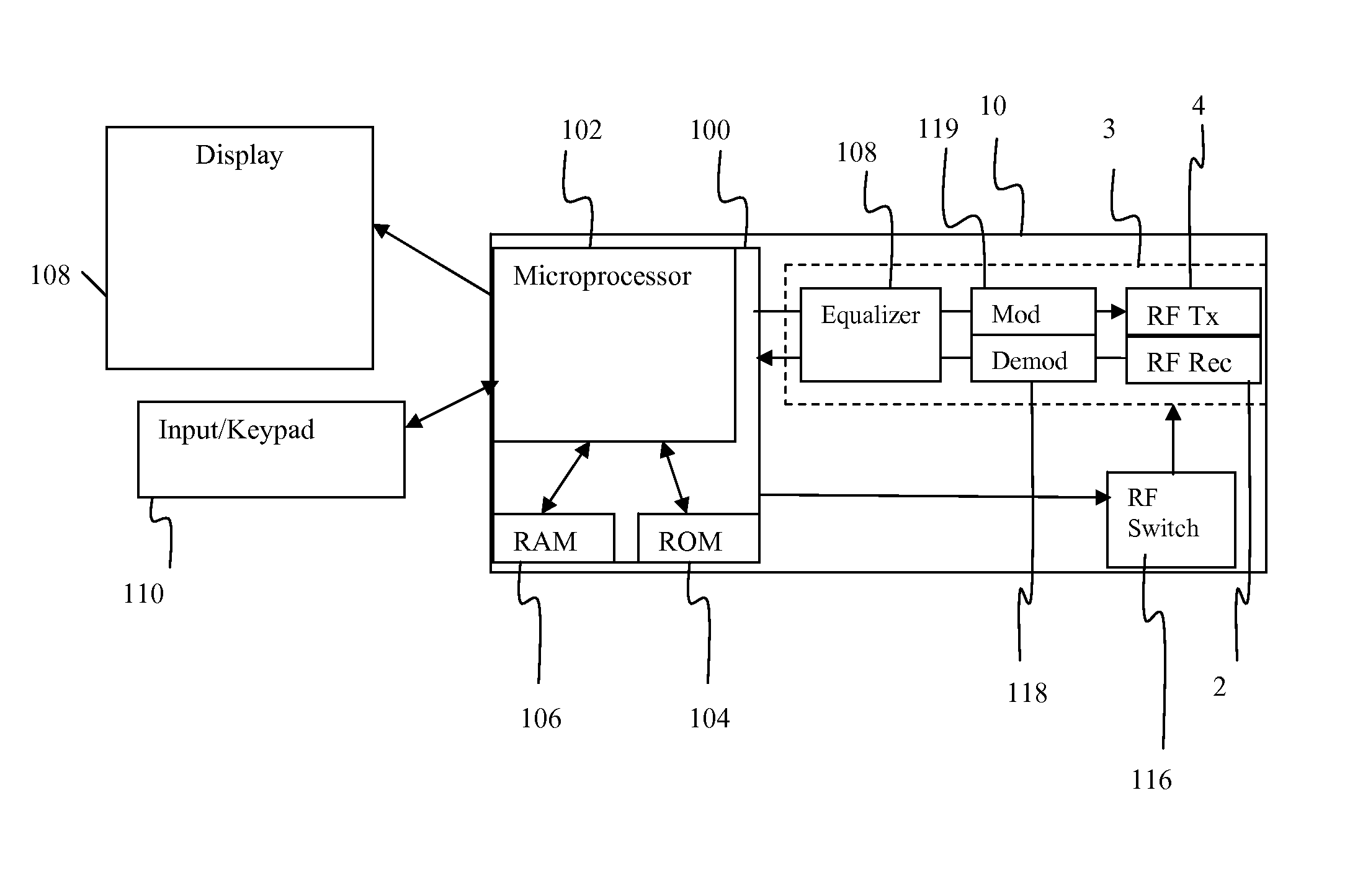
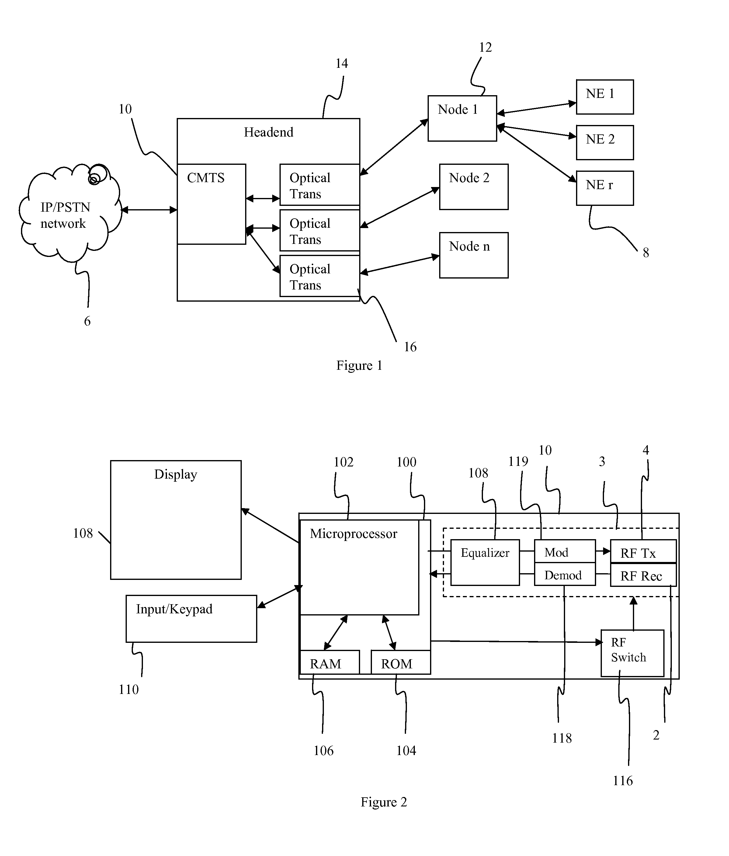
[0019]This disclosure explains an automated process to determine whether impairments, such as phase noise and / or narrowband interference are appreciably degrading the upstream plant performance in conjunction with measurements made at the headend via a CMTS device. Additionally, this process determines the highest modulation complexity that may be supported with respect to the upstream HFC plant performance. This process preferably uses only DOCSIS terminal devices in conjunction with measurements made at the headend via a DOCSIS CMTS device, and does not require rolling trucks to remote locations within a plant or specialized test equipment.

[0020]Adequate margin should preferably be available in the network to allow the addition of 2 DOCSIS channels. A methodology for determining the available power margin in a network is described in commonly assigned disclosure Attorney Docket No. BCS04121, entitled METHOD AND APPARATUS FOR DETERMINING THE TOTAL POWER MARGIN AVAILABLE FOR AN HFC ...


PUM


Abstract

The available modulation schemes of a network are analyzed to determine which ones contain excessive phase noise or narrowband interference. A network element is selected and assigned to a test channel at a first modulation scheme at a predetermined power level to achieve a predetermined PER. The network element transmits a test signal and the network controller measures the signal to noise ratio (SNR) in the received test signal. If the SNR is not within a predetermined tolerance range of an estimated SNR for the modulation scheme at the predetermined PER, the modulation scheme is determined to have excessive phase noise or narrowband interference. Each available modulation scheme is tested by instructing the network element to transmit the test signal using each modulation scheme and assigning the power level of each modulation scheme. The suitable modulation schemes may be determined.

Description

[0001]This application claims the benefit of U.S. Provisional Application No. 60 / 863,068 filed on Oct. 26, 2006 titled Method To Diagnose Phase Noise And / Or Narrowband Interference Limitations Within An Upstream Hfc Plant, herein incorporated by reference in its entirety.FIELD OF THE INVENTION[0002]This disclosure is directed toward characterizing modulation schemes in a HFC network. More particularly, this disclosure is directed toward an automated approach to analyze available modulation schemes for phase noise and narrowband interference in a HFC network.BACKGROUND OF THE INVENTION[0003]Hybrid fiber coaxial (HFC) cable television systems have been in widespread use for many years and extensive networks have been developed. A typical HFC network generally contains a headend which provide communications between user in the HFC network and the IP / PSTN networks. The headend usually contains a cable modem termination system (CMTS) containing several receivers, each receiver handling c...

Claims


Application Information

Patent Timeline
Patent Type & Authority Applications(United States)
IPC IPC(8): H04J9/00
CPCH04B10/0775H04L1/002H04L1/0003H04B10/079H04L1/00
Inventor THOMPSON, ROBERT J.COOPER, MICHAEL J.MOORE, CHARLES S.MORAN III, JOHN L.
Owner GOOGLE TECH HLDG LLC
Why Eureka
Try Eureka