
Osmotic pump apparatus and associated methods

a technology of osmotic pump and pump body, which is applied in the direction of medicine preparations, pressure infusion, pill delivery, etc., can solve the problems of fluid-inconvenient closure of conventional electro-osmotic drug delivery devices, and achieve the effect of reducing the overall volume required for implanted apparatus and reducing the size of the osmotic compartmen

Inactive Publication Date: 2008-05-01
MEDTRONIC INC
View PDF99 Cites 64 Cited by
  • Summary
  • Abstract
  • Description
  • Claims
  • Application Information

AI Technical Summary

Benefits of technology

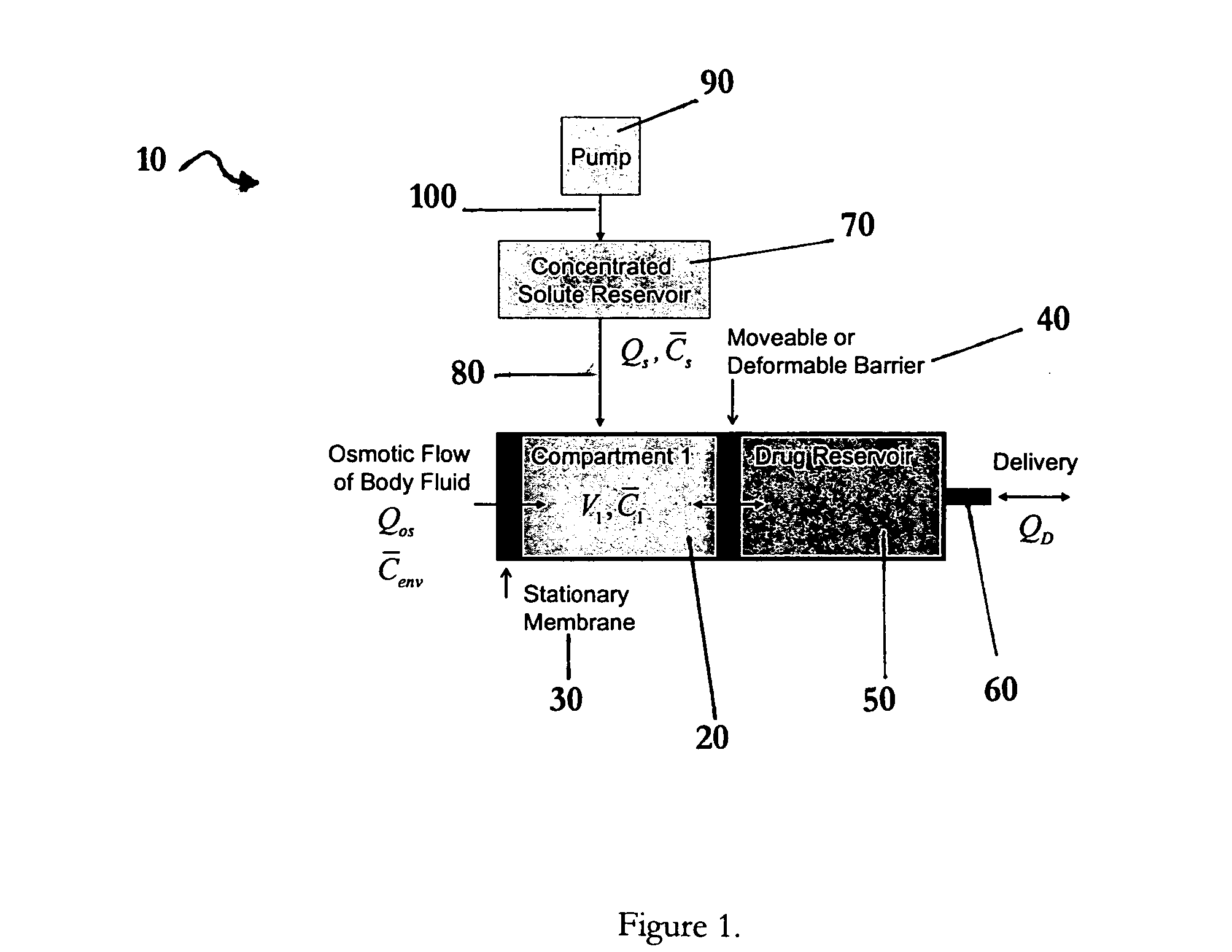
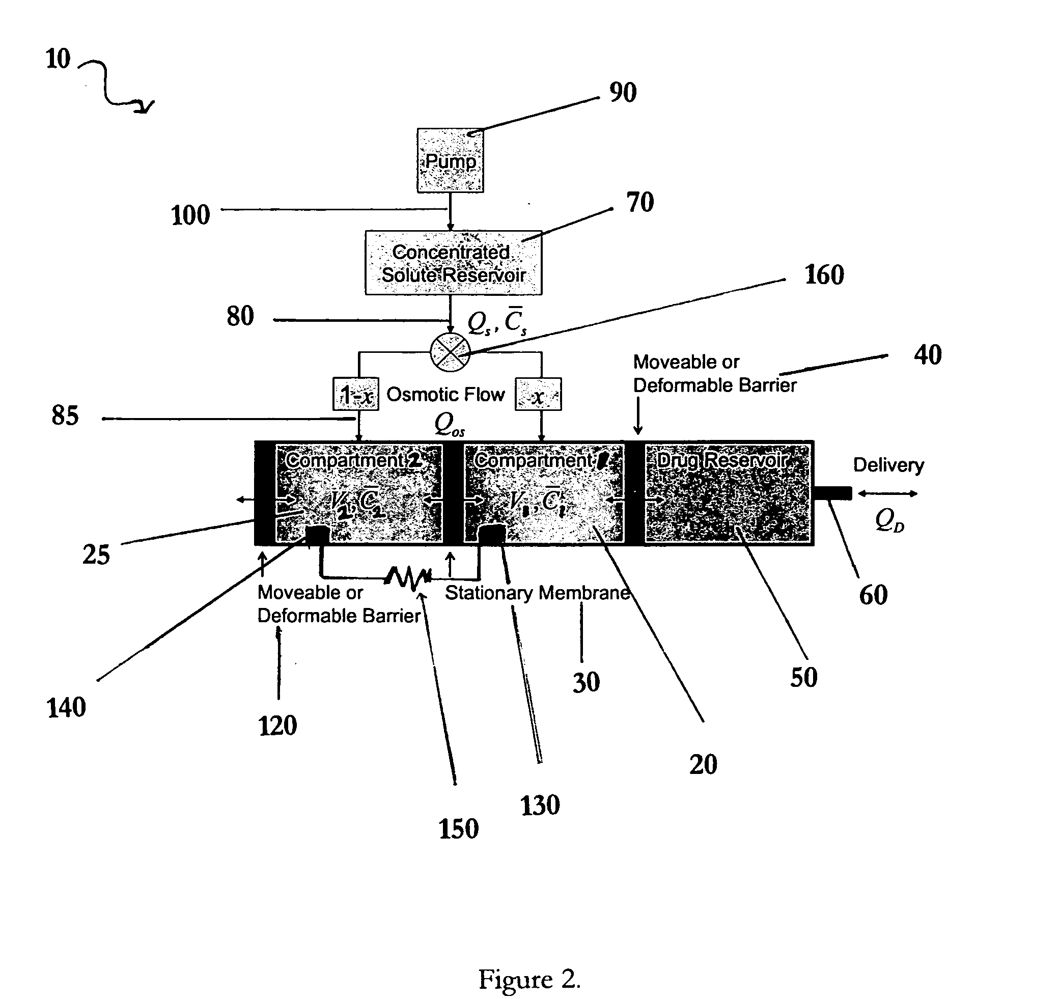
[0010]The solute reservoir used in embodiments of the invention provides both a new mechanism to precisely control osmotic pump function as well as new osmotic pump designs. For example, in the osmotic pump embodiment of the invention that is shown in FIG. 1, a steady-state mathematical model predicts that an implantable amplification device having such a solute reservoir can be constructed to convert a 1 uL / hr flowrate of saturated sodium chloride from the solute reservoir into a drug delivery rate of 28 uL / hour, (using 1 cm2 of commercially available desalination membrane). Such embodiments of the invention can consequently provide for a 28-fold reduction in the size of the osmotic compartment(s), significantly reducing the overall volume required for the implanted apparatus. Other variations of this embodiment include the temporal manipulation of the infusion rate of solute into the osmotic compartment(s) to control the drug delivery rate. In certain embodiments of the invention, the fluid delivery apparatus is an electro-osmotic apparatus as shown for example in FIGS. 2 and 4.

Problems solved by technology

Conventional electro-osmotic drug delivery devices lack closed-device means to accommodate fluid transfer between anodic and cathodic osmotic compartments.

Method used


Image

  • Osmotic pump apparatus and associated methods
  • Osmotic pump apparatus and associated methods
  • Osmotic pump apparatus and associated methods

Examples


Embodiment Construction

[0027]Unless otherwise defined, all terms of art, notations and other scientific terms or terminology used herein are intended to have the meanings commonly understood by those of skill in the art to which this invention pertains. In some cases, terms with commonly understood meanings are defined herein for clarity and / or for ready reference, and the inclusion of such definitions herein should not necessarily be construed to represent a substantial difference over what is generally understood in the art. Many of the techniques and procedures described or referenced herein are well understood and commonly employed using conventional methodology by those skilled in the art. As appropriate, procedures involving the use of commercially available kits and reagents are generally carried out in accordance with manufacturer defined protocols and / or parameters unless otherwise noted.

[0028]A number of terms are defined below.

[0029]“Fluid delivery device” and “Fluid delivery apparatus” as used...


PUM


Abstract

Apparatuses and methods for pumping fluids such as fluid medications are disclosed. Embodiments of the invention provide an osmotic pump fluid delivery apparatus including elements designed to control the fluid delivery rate. Typical embodiments of the invention include an arrangement of elements such as solute reservoirs that can manipulate the solute concentrations within an inner osmotic compartment or compartments of an osmotic pump so as to control fluid delivery from the pump. Other embodiments include sealed electro-osmotic pumps that do not discharge ions into the surroundings or require water from an external source. These embodiments of the invention provide new ways to control fluid delivery in apparatuses that employ osmotic processes to function.

Description

BACKGROUND OF THE INVENTION[0001]1. Field of the Invention[0002]This invention relates generally to osmotic pump apparatuses and associated methods for delivering fluids such as fluid medications.[0003]2. Description of the Related Art[0004]In a number pathological conditions, it is desirable to deliver fluids such as fluid medications gradually over a period of time. A common apparatus for the gradual administration of fluids into the human body is an intravenous administration set, one in which gravity induced hydrostatic infusion dispenses a fluid from a suspended bottle or bag above the patient. Additional devices and methods for the gradual administration of fluids have been devised for example to provide patients with greater mobility and include for example devices that utilize osmosis for fluid delivery. Osmosis is the transfer of a solvent, e.g., water, across a barrier, generally from an area of lesser solute concentration to an area of greater solute concentration. A vari...

Claims


Application Information

Patent Timeline
IPC IPC(8): A61K9/24A61K9/22
CPCA61K9/0004A61K9/0024A61M5/14276A61M2039/242A61M5/14593A61M5/172A61M2005/14513A61M5/14526
Inventor GROVENDER, ERIC A.JOSHI, ASHOK V.GORDON, JOHN HOWARDBHAVARAJU, SAIVAN ANTWERP, WILLIAM P.
Owner MEDTRONIC INC
Learn More