Driver device, physical quantity measuring device, and electronic instrument

a technology of physical quantity and drive device, which is applied in the direction of acceleration measurement using interia force, simultaneous indication of multiple variables, instruments, etc., can solve the problems of increasing the size and cost of vibrating gyroscope (vibrating gyrosensor), difficult to cause the crystal vibrator with a high q value to operate at its driving frequency, and increasing the size of oscillations

Inactive Publication Date: 2008-05-08
SEIKO EPSON CORP
View PDF10 Cites 37 Cited by
  • Summary
  • Abstract
  • Description
  • Claims
  • Application Information

AI Technical Summary

Benefits of technology

[0017] the driver device causing the vibrator to produce the driving vibrations using the signal modulated by the modulation circuit, and then causing the vibrator to produce the driving vibrations by controlling the oscillation amplitude in the oscillation loop formed by the vibrator and the gain control amplifier.

Problems solved by technology

This results in an increase in size and cost of a vibrating gyroscope (vibrating gyrosensor).
According to the technology disclosed in JP-A-2004-286503, it is difficult to cause the crystal vibrator with a high Q value to operate at its driving frequency because the crystal vibrator is driven at another frequency during startup.
causing oscillations to grow using the selected signal component as a cause of oscillations.

Method used


Image

  • Driver device, physical quantity measuring device, and electronic instrument
  • Driver device, physical quantity measuring device, and electronic instrument
  • Driver device, physical quantity measuring device, and electronic instrument

Examples


first embodiment

1. Driver Device

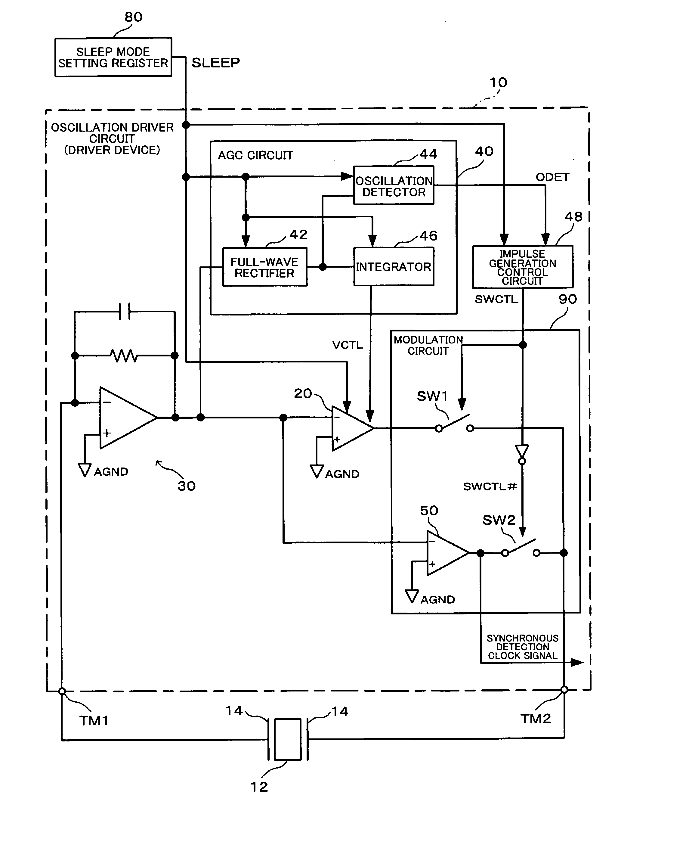
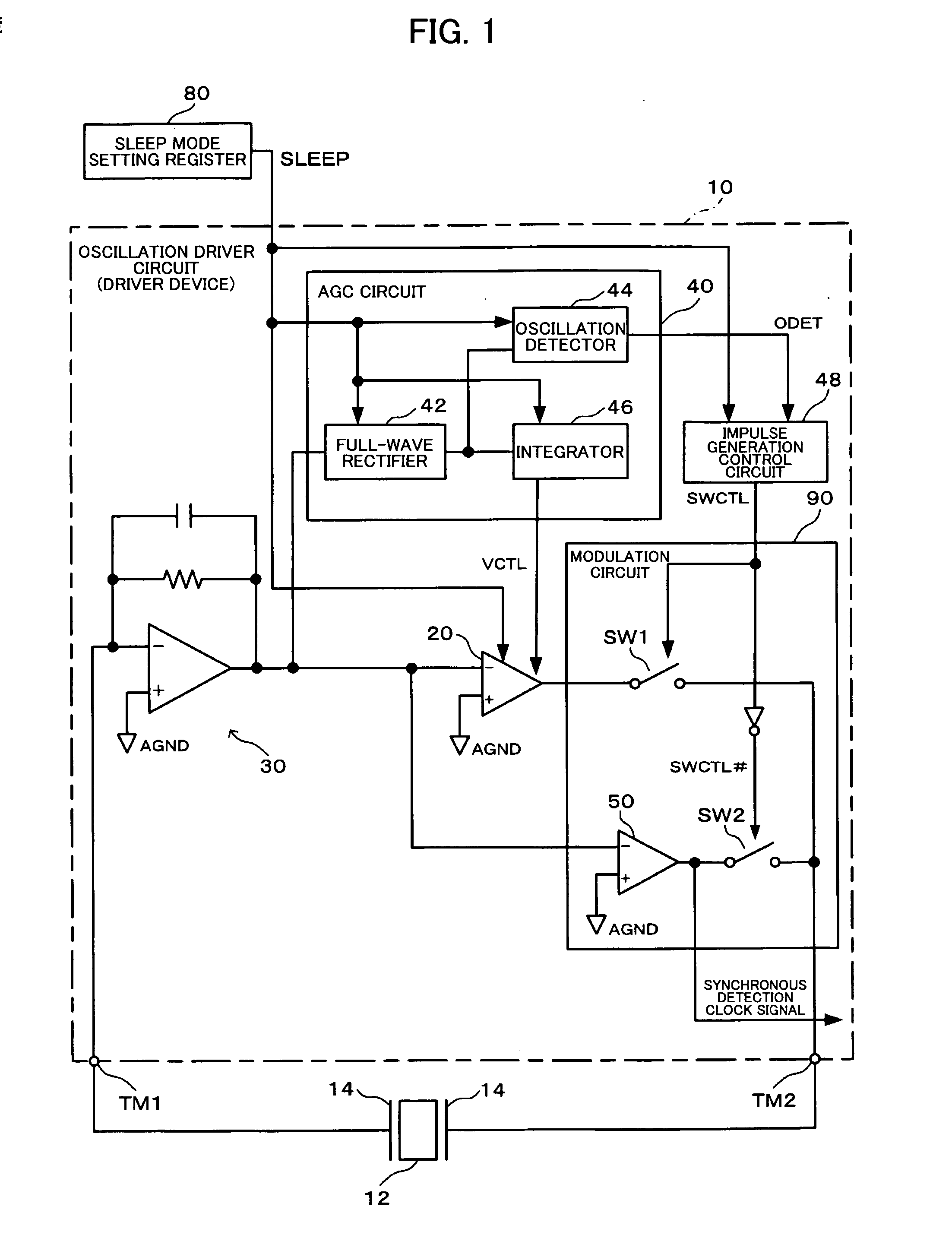
[0132]FIG. 1 is a block diagram showing a configuration example of an oscillation driver circuit (driver device) according to one embodiment of the invention. The oscillation driver circuit (driver device) according to this embodiment is used to measure a physical quantity using an output signal obtained by synchronously detecting a detection signal output from a vibrator based on driving vibrations produced by the vibrator and the physical quantity to be measured.

[0133] An oscillation driver circuit 10 includes first and second connection terminals TM1 and TM2 (electrodes or pads). A vibrator 12 is inserted between the first and second connection terminals outside the oscillation driver circuit 10. An excitation means 14 is attached to the vibrator 12. The excitation means 14 is connected with the oscillation driver circuit 10 to form an oscillation loop. An oscillation starts in a state in which the gain of a driver provided in the oscillation driver circuit 10 i...

second embodiment

2. Configuration and Operation of Vibrating Gyrosensor

[0275]FIG. 16 is a block diagram showing a configuration example of a vibrating gyrosensor to which the oscillation driver circuit according to this embodiment or its modification is applied.

[0276] In FIG. 16, the same sections as in FIG. 1 are indicated by the same symbols. Description of these sections is appropriately omitted.

[0277] A vibrating gyrosensor (physical quantity measuring device in a broad sense) 100 includes an oscillation circuit 200 and a detection circuit (detection device in a broad sense) 300. The oscillation circuit 200 includes the vibrator 12 and the oscillation driver circuit 10. The oscillation driver circuit 10 causes a driving vibration section 12a of the vibrator 12 to oscillate.

[0278] During oscillation startup in the normal mode, the output from the comparator 50 is input to the oscillation driver circuit 10 as noise. The noise is subjected to frequency selection while passing through the drivin...


PUM


Abstract

A driver device includes a gain control amplifier that causes a vibrator to produce driving vibrations by controlling an oscillation amplitude in an oscillation loop, a signal generation circuit that generates a signal having a given frequency, and a modulation circuit that modulates the frequency of the signal generated by the signal generation circuit to a resonance frequency of the vibrator. The driver device causes the vibrator to produce the driving vibrations using the signal modulated by the modulation circuit, and then causes the vibrator to produce the driving vibrations by controlling the oscillation amplitude in the oscillation loop formed by the vibrator and the gain control amplifier.

Description

[0001] Japanese Patent Application No. 2006-300080 filed on Nov. 6, 2006 and Japanese Patent Application No. 2007-282053 filed on Oct. 30, 2007, are hereby incorporated by reference in their entirety. BACKGROUND OF THE INVENTION [0002] The present invention relates to a driver device which causes a vibrator to produce driving vibrations, a physical quantity measuring device (e.g. vibrating gyroscope) using the driver device, an electronic instrument, and the like. [0003] Gyroscopes are classified as a rotating gyroscope, a vibrating gyroscope, and the like depending on the method of detecting the force applied to an object. In particular, a vibrating gyroscope is considered to be advantageous for reducing size and cost from the viewpoint of the constituent elements and the like. As a vibrating gyrosensor which detects an angular velocity applied to an object, a piezoelectric vibrating gyrosensor is known which excites a crystal or a piezoelectric element that is advantageous for inc...

Claims


Application Information

Patent Timeline
Patent Type & Authority Applications(United States)
IPC IPC(8): G01P9/04G01P15/097H03B5/36
CPCG01C19/5649H03B2200/0046H03B5/36G01P15/097H03B5/06
Inventor KANAI, MASAHIROYOSHIDA, NAOKIOTSUKA, EITARO
Owner SEIKO EPSON CORP
Why Eureka
Try Eureka