

Parallel Flow Heat Exchanger With Crimped Channel Entrance
Inactive Publication Date: 2008-05-08
CARRIER CORP
View PDF16 Cites 36 Cited by
- Summary
- Abstract
- Description
- Claims
- Application Information
AI Technical Summary
Benefits of technology
[0011]The objective of the invention is to introduce a pressure drop control for the parallel flow evaporator that will essentially equalize pressure drop through the heat exchanger channels and therefore eliminate refrigerant maldistribution and the problems associated with it. Further, it is the objective of the present invention to provide refrigerant expansion at the entrance of each channel, thus eliminating a predominantly two-phase flow in the inlet manifold and preventing phase separation, which is one of the main causes for refrigerant maldistribution.
[0013]In both cases outlined above, but especially if the crimping restrictions are provided as primary expansion devices at the entrance of each channel of the parallel flow evaporator, they represent a major resistance to the refrigerant flow within the evaporator. In such circumstances, the main pressure drop region will be across these restrictions and the variations in the pressure drop in the channels or in the manifolds of the parallel flow evaporators will play a minor (insignificant) role. Further, since refrigerant expansion is taking place at the entrance of each channel, a predominantly single-phase liquid refrigerant is flown through the inlet manifold and no phase separation occurs prior to entering individual evaporator channels. Hence, uniform refrigerant distribution is achieved, evaporator and system performance is enhanced, flooding conditions at the compressor suction are avoided and, at the same time, precise superheat control is not lost (whenever required). Furthermore, low extra cost for the proposed method makes this invention very attractive.
Problems solved by technology
It causes significant evaporator and overall system performance degradation over a wide range of operating conditions.
Maldistribution of refrigerant may occur due to differences in flow impedances within evaporator channels, non-uniform airflow distribution over external heat transfer surfaces, improper heat exchanger orientation or poor manifold and distribution system design.
Attempts to eliminate or reduce the effects of this phenomenon on the performance of parallel flow evaporators have been made with little or no success.
The primary reasons for such failures have generally been related to complexity and inefficiency of the proposed technique or prohibitively high cost of the solution.
The evaporator applications, although promising greater benefits and rewards, are more challenging and problematic.
Refrigerant maldistribution is one of the primary concerns and obstacles for the implementation of this technology in the evaporator applications.
As known, refrigerant maldistribution in parallel flow heat exchangers occurs because of unequal pressure drop inside the channels and in the inlet and outlet manifolds, as well as poor manifold and distribution system design.
Furthermore, the recent trend of the heat exchanger performance enhancement promoted miniaturization of its channels (so-called minichannels and microchannels), which in turn negatively impacted refrigerant distribution.
Since it is extremely difficult to control all these factors, many of the previous attempts to manage refrigerant distribution, especially in parallel flow evaporators, have failed.
If, on the other hand, the velocity of the two-phase flow entering the manifold is low, there is not enough momentum to carry the liquid phase along the header.
Also, the liquid and vapor phases in the inlet manifold can be separated by the gravity forces, causing similar maldistribution consequences.
In either case, maldistribution phenomenon quickly surfaces and manifests itself in evaporator and overall system performance degradation.
Moreover, maldistribution phenomenon may cause the two-phase (zero superheat) conditions at the exit of some channels, promoting potential flooding at the compressor suction that may quickly translate into the compressor damage.
Method used
View moreImage
Smart ImageViewing Examples

Examples
second embodiment
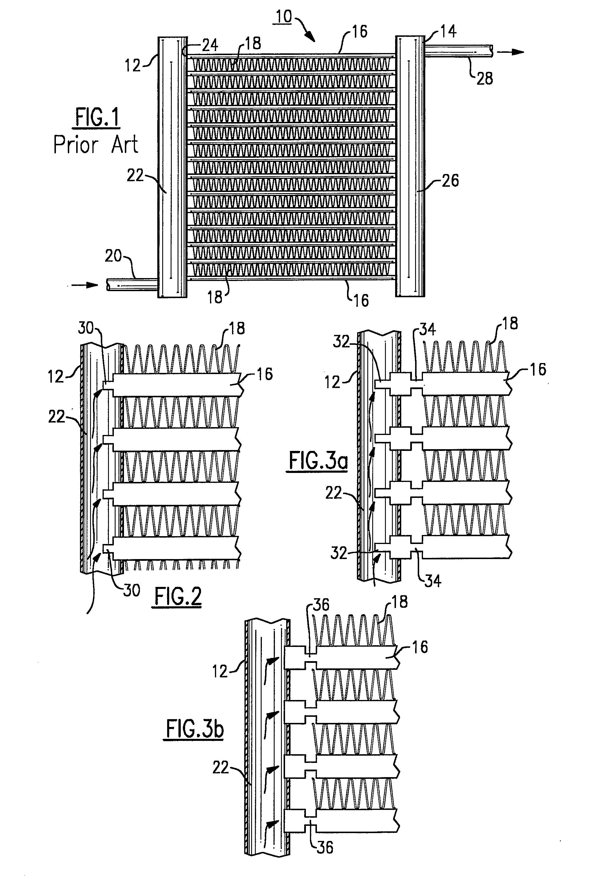
[0030]In the invention, as illustrated in FIG. 3a, the channels are crimped at the very end 32 and at a point 34, some distance away from the end and the attachment point to the manifold 12.
third embodiment
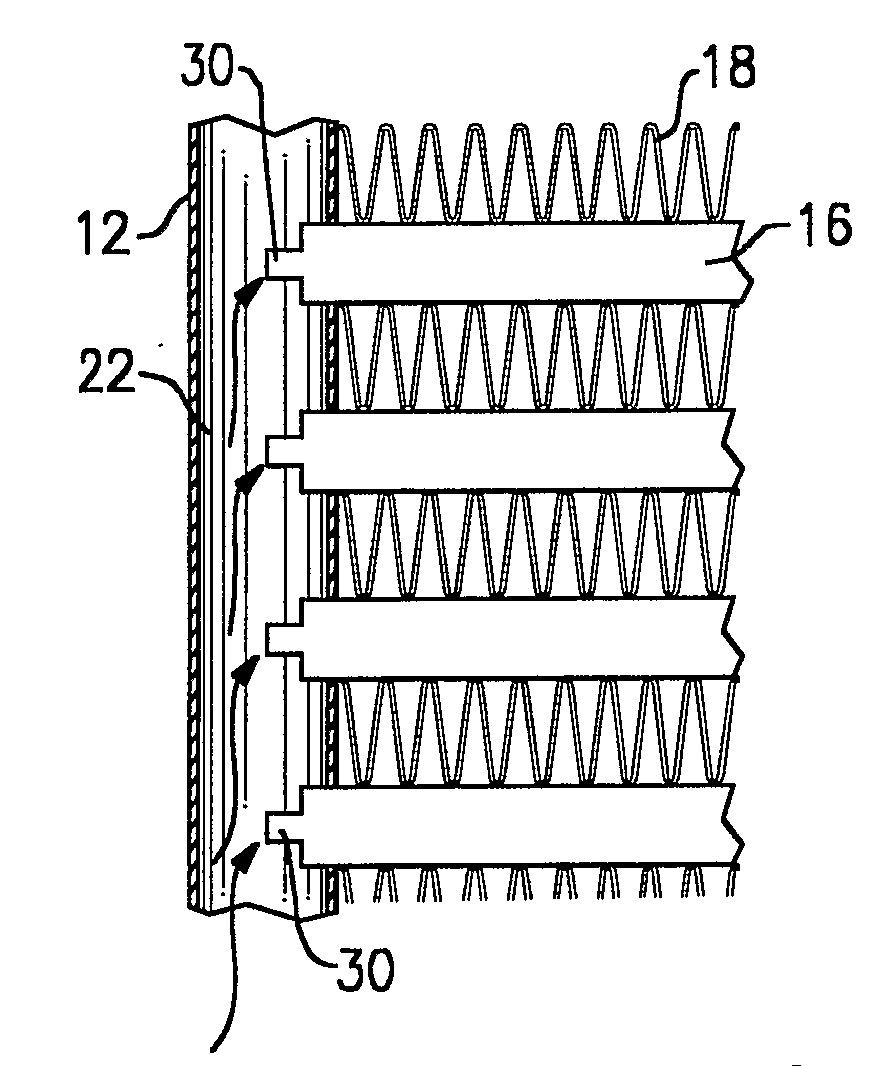
[0031]In a third embodiment, as illustrated in FIG. 3b, the channels are crimped at a single location 36, a predetermined distance from the channel end and, once again, away form the attachment point to the manifold 12, in order not to interfere with the attachment process.
fourth embodiment
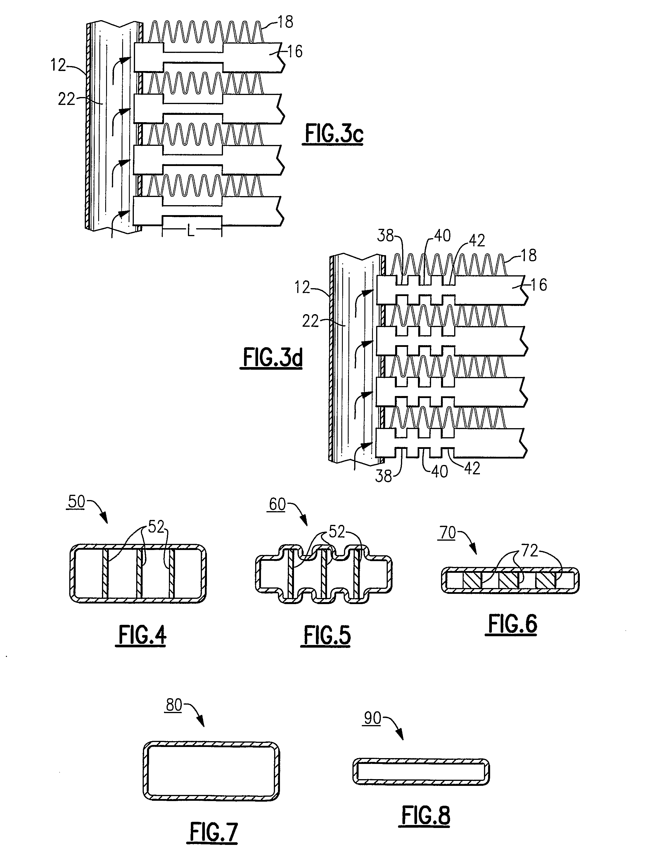
[0032]In a fourth embodiment, as illustrated in FIG. 3c, the channels are crimped for a predetermined length or distance “L” near the channel ends but with less cross-section area alteration / reduction than in FIGS. 2, 3a and 3b.
Login to View More PUM
 Abstract
A parallel flow (minichannel or microchannel) evaporator includes channels which are crimped at or adjacent to their entrance location which provides for a refrigerant expansion and pressure drop control resulting in the elimination of refrigerant maldistribution in the evaporator and prevention of potential compressor flooding. Progressive crimping to counter-balance factors effecting refrigerant distribution is also disclosed.
Description
CROSS-REFERENCE TO RELATED APPLICATION[0001]Reference is made to and this application claims priority from and the benefit of U.S. Provisional Application Ser. No. 60 / 649,383, filed Feb. 2, 2005, and entitled PARALLEL FLOW EVAPORATOR WITH CRIMPED CHANNEL ENTRANCE, which application is incorporated herein in its entirety by reference.BACKGROUND OF THE INVENTION[0002]This invention relates generally to air conditioning, heat pump and refrigeration systems and, more particularly, to parallel flow evaporators thereof.[0003]A definition of a so-called parallel flow heat exchanger is widely used in the air conditioning and refrigeration industry and designates a heat exchanger with a plurality of parallel passages, among which refrigerant is distributed and flown in the orientation generally substantially perpendicular to the refrigerant flow direction in the inlet and outlet manifolds. This definition is well adapted within the technical community and will be used throughout the text.[00...
Claims
Login to View More Application Information
Patent Timeline
 IPC IPC(8): F28F9/02
CPCF25B39/00F25B41/067F25B2500/01F28F2260/02F28D2021/0071F28F1/025F28F9/0282F28D1/05366F25B41/37F28F9/02F28F9/00
InventorTARAS, MICHAEL F.LIFSON, ALEXANDERGORBOUNOV, MIKHAIL B.
OwnerCARRIER CORP