Gravity Separator For A Multi-Phase Effluent

a gravity separator and effluent technology, applied in the field of gravity separators, can solve the problems of unburnt hydrocarbons and environmental pollution, inconvenient adjustment and maintenance of the separator, and the inability of the separator to handle the effluent well, etc., and achieve the effect of convenient adjustment and maintenan

Inactive Publication Date: 2008-05-08
SCHLUMBERGER TECH CORP
View PDF26 Cites 19 Cited by
  • Summary
  • Abstract
  • Description
  • Claims
  • Application Information

AI Technical Summary

Benefits of technology

[0028]Consequently, the gravity separator of the invention does not require any mechanical actuator to position the collector in the phase. Further, the gravity separator according to the invention is simple, auto-adjustable and easy to adjust and maintain.

Problems solved by technology

Such separator is not well adapted to handle the effluent with substantially varying phase fractions as encountered at the beginning of the clean-up period.
This solution results in un-burnt hydrocarbons and environmental pollution problem.
The last two solutions result in costly and voluminous equipment.

Method used


Image

  • Gravity Separator For A Multi-Phase Effluent
  • Gravity Separator For A Multi-Phase Effluent
  • Gravity Separator For A Multi-Phase Effluent

Examples


Embodiment Construction

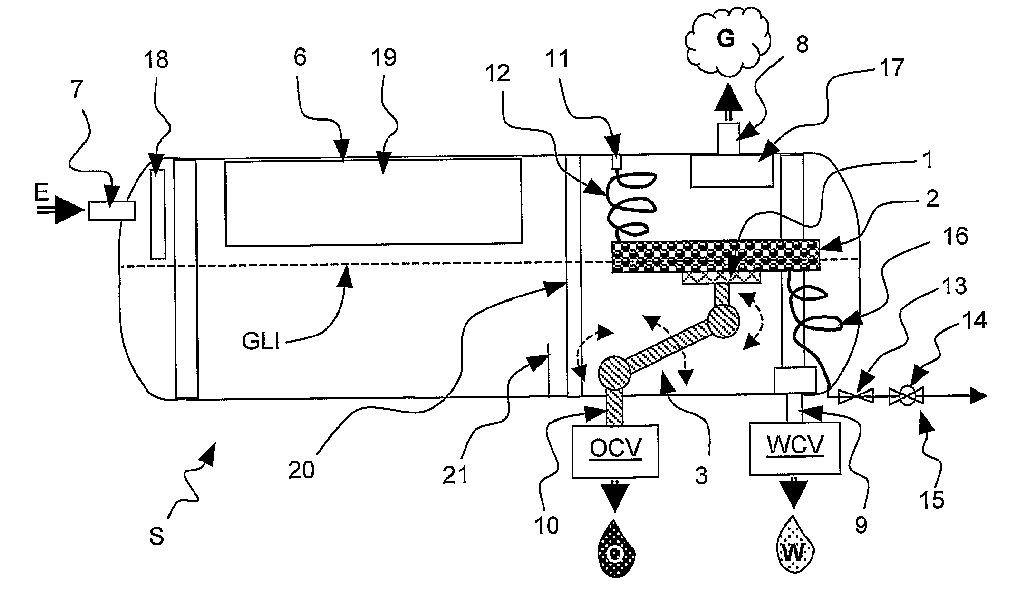
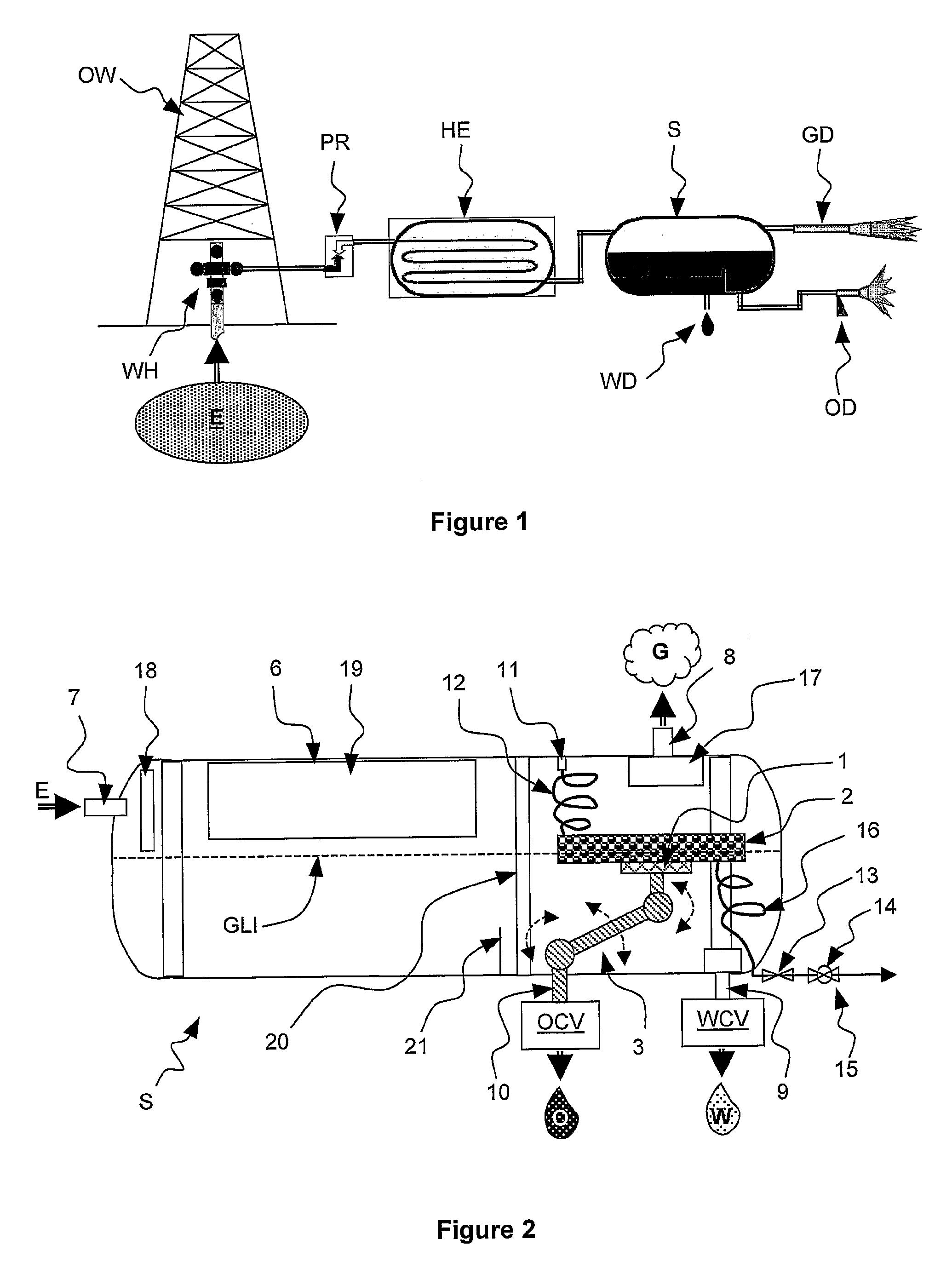
[0038]FIG. 2 shows a schematic cross-section view of a separator according to a preferred embodiment of the invention. This embodiment relates to an articulated adjustable collecting assembly.

[0039]An effluent E to be treated penetrates in the separator S trough an effluent inlet 7. The effluent E is for example a multiphase fluid mixture provided by an hydrocarbon well after having passed a solids separator, a pressure reducer and a heat exchanger.

[0040]The separator S usually comprises a vessel 6 under the form of a cylindrical tank of approximately 4 m3 capacity. The vessel size is a compromise between effluent capacity and transportability: the separator is advantageously transportable from one hydrocarbon well site to another. The separator operates according to the well known principle of the different phases of the effluent settling out by gravity.

[0041]In the particular application of the separator to the oil industry, the separator is a three-phase separator that separates ...


PUM

PropertyMeasurementUnit
gravityaaaaaaaaaa
pressureaaaaaaaaaa
flexibleaaaaaaaaaa

Abstract

A gravity separator S separates a liquid phase O and a gas phase G from a multiphase fluid mixture E. The gravity separator comprises a collector 1 for collecting the liquid phase O, and outlet 8 for extracting the gas phase G and a draining circuit 3 coupled to the collector 1 for draining the liquid phase O out of the separator.
The gravity separator S further comprises a floating assembly 2 coupled to the collector 1. The floating assembly is arranged to float at an interface GLI between the liquid phase and the gas phase so that the collector is positioned in the multiphase fluid mixture present in the gravity separator S for collecting substantially the liquid phase O.

Description

FIELD OF THE INVENTION[0001]The invention relates to a gravity separator for separating different phases of a multiphase effluent.[0002]A particular application of the invention relates to a separator for an effluent from a hydrocarbon well. Such an effluent typically comprises three phases: an aqueous phase, a liquid hydrocarbon phase and a gaseous hydrocarbon phase.BACKGROUND OF THE INVENTION[0003]After a hydrocarbon well has been drilled and made safe, a well testing operation is generally carried out for a short period of time. The well testing operation serves to characterize the various components of the well, and to estimate the production capacities of the well. An aspect of the test is to separate certain phases of the effluent, typically water, oil, and gas. Since the various phases are of different densities, separation takes place continuously in a gravity separator, in which the phases settle out. The gravity separator can be a vertical or a horizontal separator.[0004]F...

Claims


Application Information

Patent Timeline
Patent Type & Authority Applications(United States)
IPC IPC(8): B01D17/025B01D17/02B01D21/24E02B15/04
CPCB01D17/0211B01D19/0036B01D21/2444B01D17/0214
Inventor ALLOUCHE, FRANCIS
Owner SCHLUMBERGER TECH CORP
Why Eureka
Try Eureka