Method and system for enhanced cutter throughput

a technology of input system and cutter, which is applied in the directions of pile separation, transportation and packaging, printing, etc., can solve problems such as system inability, and achieve the effects of improving throughput, less delay, and efficient cutting

Active Publication Date: 2008-05-08
DMT SOLUTIONS GLOBAL CORP
View PDF7 Cites 14 Cited by
  • Summary
  • Abstract
  • Description
  • Claims
  • Application Information

AI Technical Summary

Benefits of technology

[0016]The present invention represents an improvement over the prior art by providing improved throughput. Instead of performing two single cuts wh...

Problems solved by technology

A frequent limitation on speed of an inserter system is the ability of the system to handle all of the generated documents if the system is required to stop.
An input system may...

Method used


Image

  • Method and system for enhanced cutter throughput
  • Method and system for enhanced cutter throughput
  • Method and system for enhanced cutter throughput

Examples


Embodiment Construction

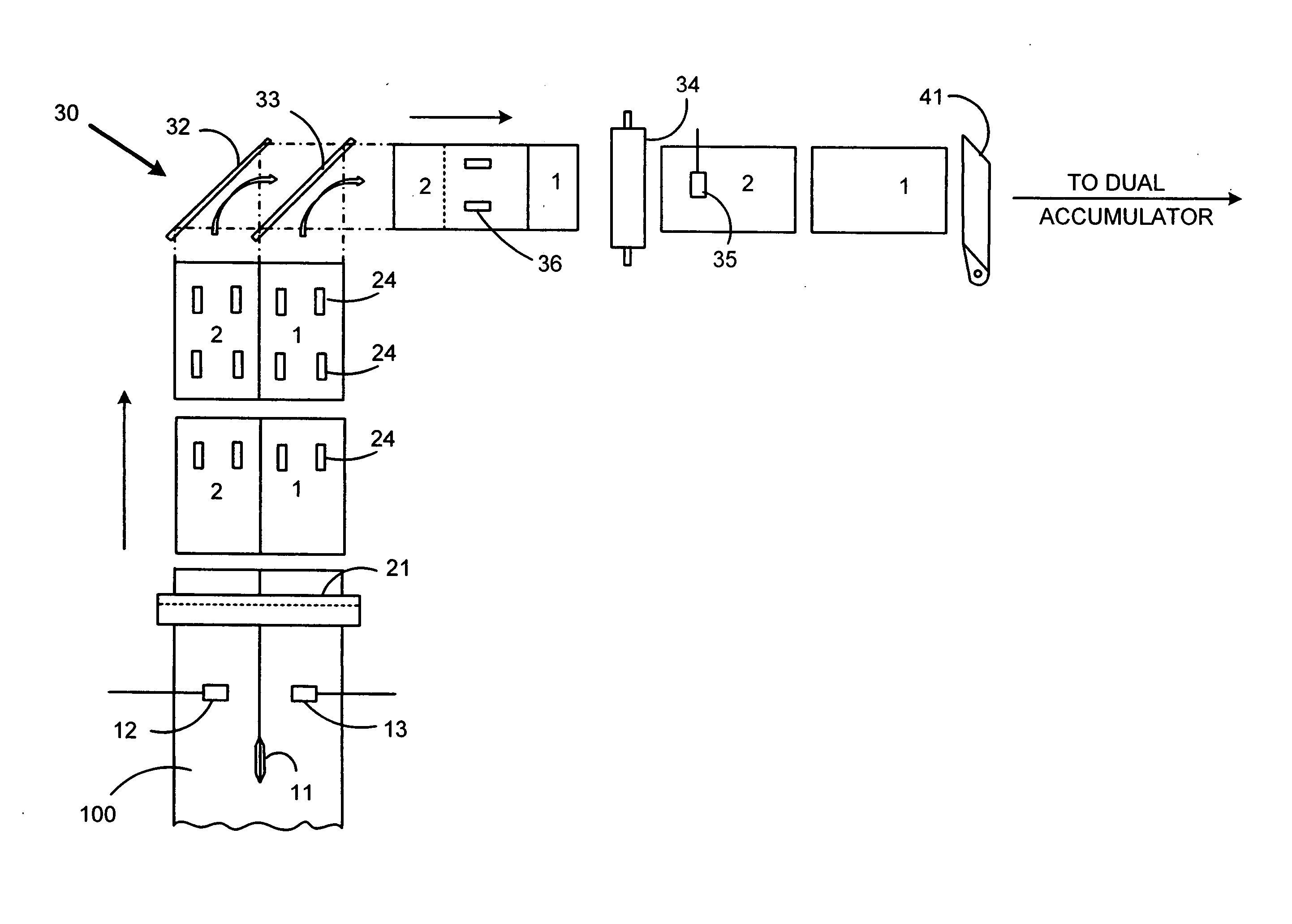
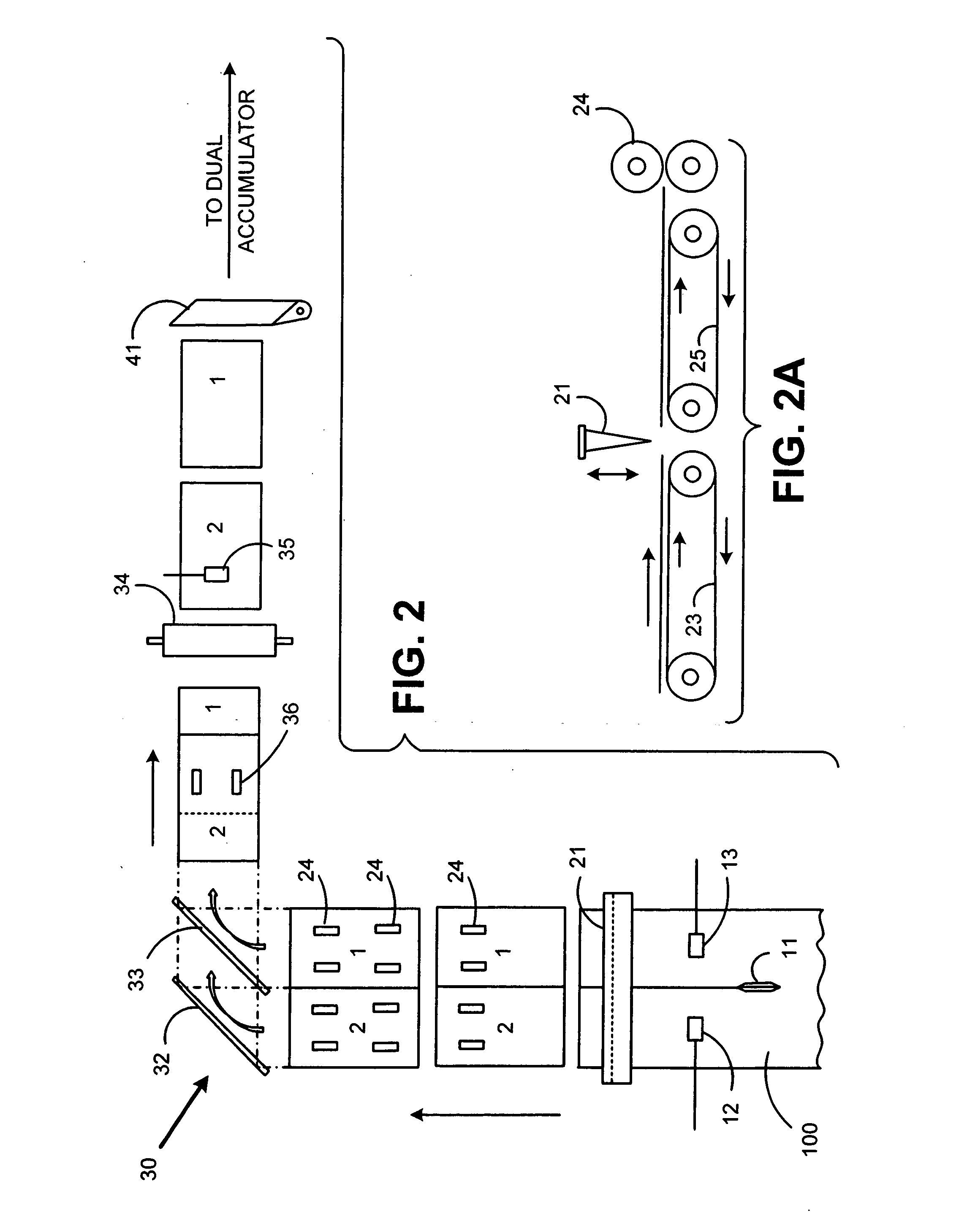
[0030]A preferred embodiment for implementing the present invention is depicted in FIG. 2. The components depicted in FIG. 2 may be associated with the general input stages depicted in FIG. 1, however it is not necessary that the particular components be part of any particular module, so long as they perform as described herein.

[0031]A web 100 is drawn into the inserter input subsystem. Methods for transporting the web are known and may include rollers, or tractors pulling on holes along a perforated strip at the edges of the web. The web 100 is split into two side-by-side portions by a cutting device 11. Cutting device 11 may be a stationary knife or a rotating cutting disc, or any other cutting device known in the art. While the embodiment in FIG. 2 shows the web being split into two portions, one skilled in the art will understand that a plurality of cutting devices 11 may be used to create more than two strands of web from the original one. Further, the processing steps describe...


PUM

PropertyMeasurementUnit
Angleaaaaaaaaaa
Speedaaaaaaaaaa

Abstract

An improved inserter input system and method for transversely cutting a web of printed material into separate sheets, the web including a plurality of separated side-by-side sheets. A set of sheets on the web is transported to the cutting device. One or more of the sheets in the set belongs to a new collation for which sheets have not previously been cut. The system determines whether sufficient collation parking spots exist to accommodate a new collation. If there are no available collation parking spots, and if all of the sheets in the set belong to the new collation, then transverse cutting is delayed until an open collation parking spot becomes available. If there are no available collation parking spots, and if a subset of sheets belong to a prior collation, then the web is partially cut to separate only the sheet, or sheets, that belong to the prior collation. The cutting of the other sheet(s) is delayed until the open collation parking spot becomes available. If there is an available collation parking spot, then the cutting device transversely cuts the entire set of side-by-side sheets.

Description

TECHNICAL FIELD[0001]The present invention relates to an inserter input system for generating sheets of printed material to be collated and inserted into envelopes. Such an inserter input system cuts and processes a continuous web of material into individual sheets. The individual sheets may then be processed into mail pieces.BACKGROUND OF THE INVENTION[0002]Inserter systems, such as those applicable for use with the present invention, are typically used by organizations such as banks, insurance companies and utility companies for producing a large volume of specific mailings where the contents of each mail item are directed to a particular addressee. Also, other organizations, such as direct mailers, use inserts for producing a large volume of generic mailings where the contents of each mail item are substantially identical for each addressee. Examples of such inserter systems are the 8 series, 9 series, and APST™ inserter systems available from Pitney Bowes Inc. of Stamford, Conn....

Claims


Application Information

Patent Timeline
IPC IPC(8): B41F13/58
CPCB26D5/00B65H2801/66B65H15/00B65H29/145B65H29/6609B65H35/02B65H35/04B65H39/07B65H39/11B65H2301/3423B65H2301/42132B65H2301/4311B65H2301/44514B65H2404/632B26D11/00B65H2301/4213B65H15/004
Inventor SUSSMEIER, JOHN W.SKINGER, GREGORY P.
Owner DMT SOLUTIONS GLOBAL CORP
Why Eureka
Try Eureka