Driving Device With Rotating Electric Machine

a technology of rotating electric machines and driving devices, which is applied in electric devices, propulsion using engine-driven generators, and magnetic circuit shapes/forms/construction, etc., can solve problems such as gear noise, and achieve the effects of reducing noise, increasing the apparent mass of the case, and preventing the vibration of the case itsel

Inactive Publication Date: 2008-05-08
TOYOTA JIDOSHA KK
View PDF11 Cites 33 Cited by
  • Summary
  • Abstract
  • Description
  • Claims
  • Application Information

AI Technical Summary

Benefits of technology

[0006]In a driving device with a rotating electric machine thus configured, since the first thrust end face of the stator is pressed against the inner surface of the case, the case

Problems solved by technology

In a conventional driving device with a rotating electric machine, there has been a problem that vibration caused by meshing of gears constituting the drivin

Method used


Image

  • Driving Device With Rotating Electric Machine
  • Driving Device With Rotating Electric Machine
  • Driving Device With Rotating Electric Machine

Examples


first embodiment

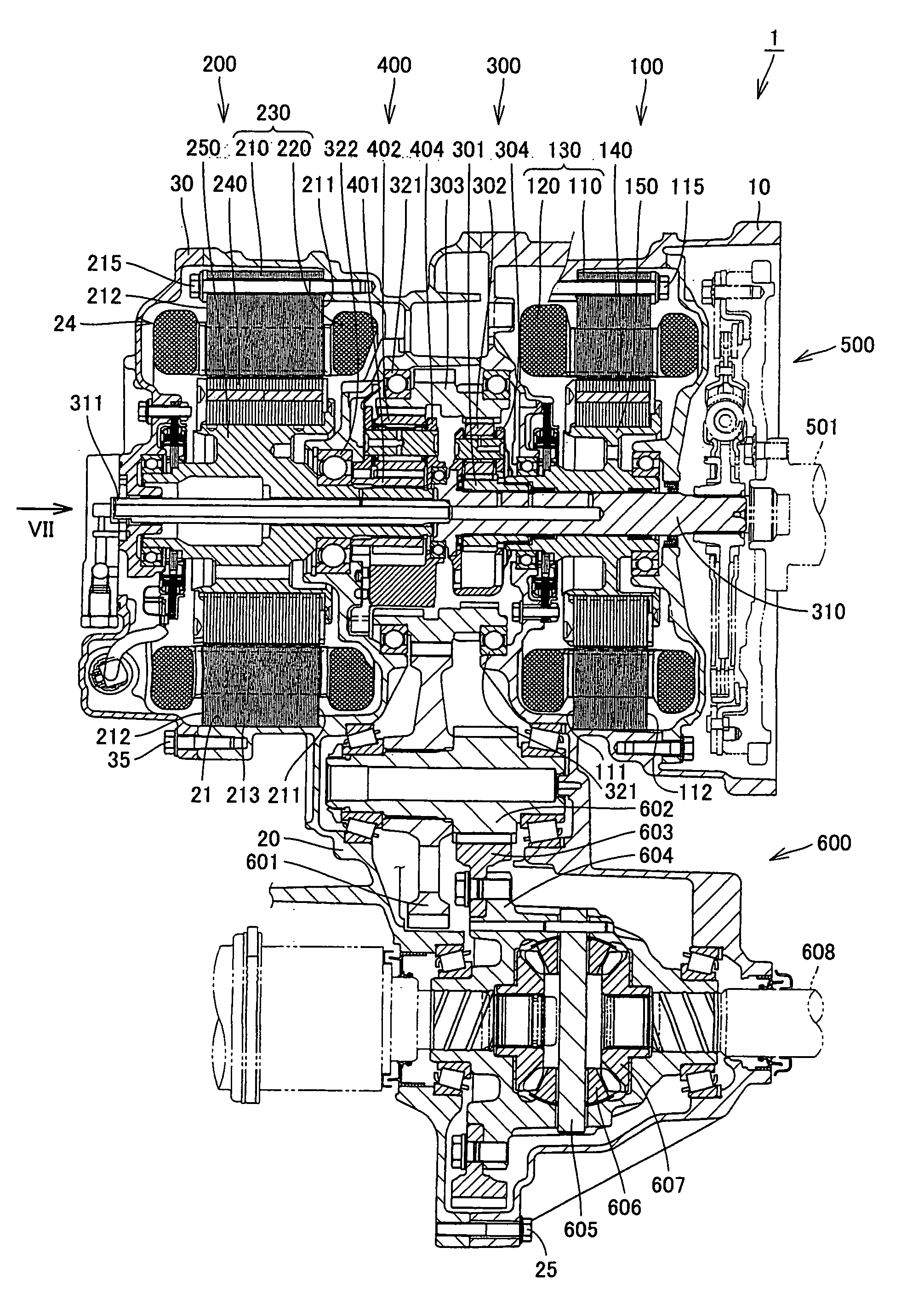
[0021]FIG. 1 is a cross-sectional view of a transaxle according to a first embodiment of the present invention. Referring to FIG. 1, a transaxle 1 according to the first embodiment of the present invention includes a transaxle housing 10, a transaxle case 20 connected to transaxle housing 10, and a transaxle rear cover 30 sealing an end of transaxle case 20. A transaxle damper 500, a first rotating electric machine 100, a second rotating electric machine 200, a front planetary gear 300, a rear planetary gear 400 and a powertrain 600 are stored in a space surrounded by transaxle housing 10, transaxle case 20 and transaxle rear cover 30.

[0022]Second rotating electric machine 200 as a motor for driving and first rotating electric machine 100 as a generator to generate electric power are contained in transaxle 1.

[0023]Transaxle damper 500 is a mechanism that transmits driving force from a shaft 501 connected to the engine and is composed of a coil spring damper. In addition, with a torq...

second embodiment

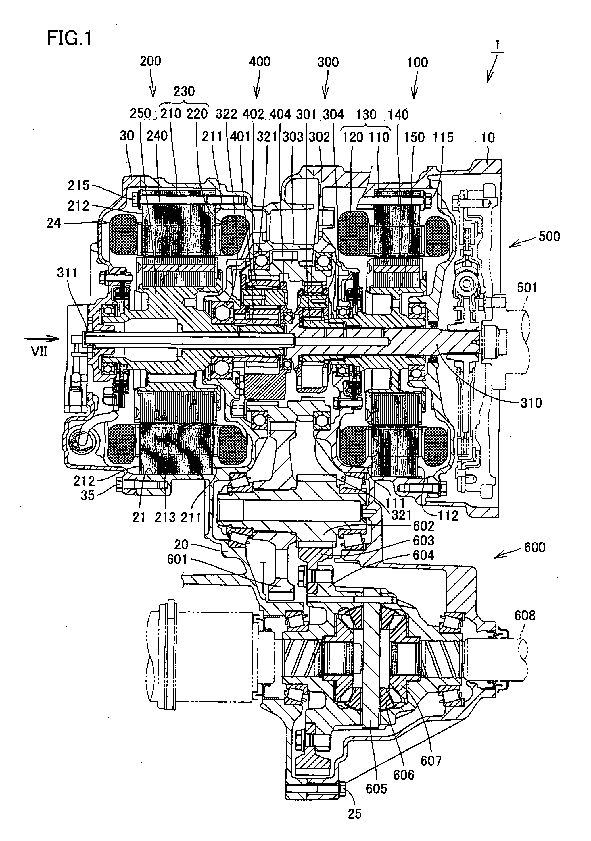
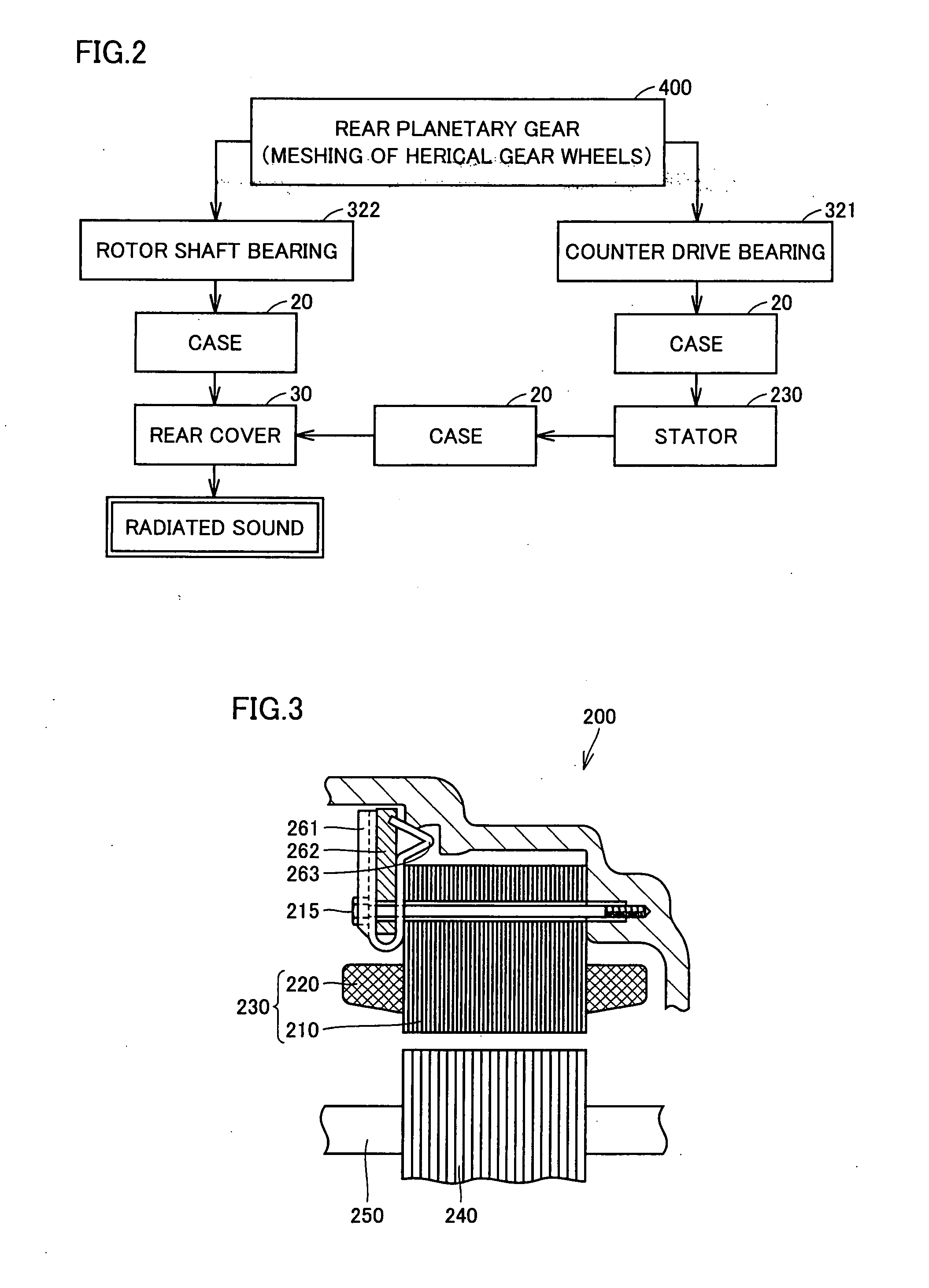
[0038]FIG. 3 is a cross-sectional view of a transaxle according to a second embodiment of the present invention. Referring to FIG. 3, in transaxle 1 according to the second embodiment of the present invention, stator 230 is fixed to transaxle case 20 by a fastener 261. Stator 230 is cantilevered in clearance fit and fixed to transaxle case 20 by bolt 215. Stator 230 is positioned with fastener 261 interposed between a bearing surface of bolt 215 and stator core 210. Fastener 261 has a leading end 263 in the form of a wedge and composed of spring steel. Leading end 263 engages between transaxle case 20 and stator core 210 to be elastically deformed. Leading end 263 may be plastically deformed. Between stator core 210 and transaxle case 20 there is provided a clearance into which a wedge of spring steel is inserted. In the present embodiment, fastener 261 is composed of spring steel, however, the present invention is not limited thereto and fastener 261 may be composed of plastic, for...

third embodiment

[0043]FIG. 6 is a cross-sectional view of a transaxle according to a third embodiment of the present invention. Referring to FIG. 6, transaxle 1 according to the third embodiment of the present invention is different from transaxle 1 according to the first embodiment in that coil 220 is in contact with transaxle rear cover 30. In other words, transaxle rear cover 30 and coil 220 are brought into contact with each other to be united in order to increase the apparent mass of transaxle rear cover 30, thereby preventing resonance of transaxle rear cover 30 and reducing occurrence of the radiated sound. In order to make the contact between transaxle rear cover 30 and coil 220 more reliable, an adhesive or the like may be interposed therebetween. In addition, a material to attenuate vibration may be interposed between transaxle rear cover 30 and coil 220.

[0044]With a thus-configured transaxle according to the third embodiment, effects similar to those of the transaxle according to the fir...


PUM


Abstract

A transaxle includes a case having an opening, a second rotating electric machine stored in the opening of the case and having a stators, a rear planetary gear stored in the transaxle case and connected to the second rotating electric machine, a transaxle rear cover sealing the opening and a bolt fixing the second rotating electric machine to the transaxle case. The stator has first and second thrust end faces defining an axial length thereof. The first thrust end face is pressed against an inner surface of the case.

Description

TECHNICAL FIELD[0001]The present invention relates to a driving device with a rotating electric machine, and more particularly, to a driving device with a rotating electric machine mounted on a vehicle.BACKGROUND ART[0002]A driving device with a rotating electric machine mounted on a vehicle has been disclosed, for example, in Japanese Patent Laying-Open No. 2004-254434 (Document 1). Japanese Patent Laying-Open Nos. 2003-191759 (Document 2), 59-209053 (Document 3), 2001-69717 (Document 4) and 2002-171717 (Document 5) disclose a rotating electric machine.DISCLOSURE OF THE INVENTION[0003]In a conventional driving device with a rotating electric machine, there has been a problem that vibration caused by meshing of gears constituting the driving device and transmitted through a case and vibration transmitted through a rotor shaft of the rotating electric machine make resonance, producing gear noise.[0004]The present invention has been made to solve the problem as mentioned above. An obj...

Claims


Application Information

Patent Timeline
IPC IPC(8): H02K7/116H02K7/18H02K5/00F16H48/30
CPCY02T10/6239B60L2220/50B60K6/365B60K6/40B60K6/405B60K6/445F16H3/727F16H57/0006F16H2037/0866F16H2200/2007H02K1/185H02K7/006H02K7/116H02K16/00B60L11/123B60L11/14B60L15/20B60L2220/42B60L2240/423B60L2240/443B60L2270/142B60L2270/145B60K6/26Y02T10/72B60L50/61B60L50/16Y02T10/62Y02T10/64Y02T10/7072Y02T10/70H02K5/00
Inventor MIZUNO, YOTASHIMADA, YUJIHATA, HIROSHIOKAWA, AKITOTANGE, KINJIYOSHII, KINYAADACHI, MASATOSHI
Owner TOYOTA JIDOSHA KK
Why Eureka
Try Eureka