
Apparatus for adjusting frequency characteristic and q factor of low pass filter and method thereof

Inactive Publication Date: 2008-05-08
ELECTRONICS & TELECOMM RES INST
View PDF6 Cites 0 Cited by
  • Summary
  • Abstract
  • Description
  • Claims
  • Application Information

AI Technical Summary

Benefits of technology

[0017]An embodiment of the present invention is directed to providing an apparatus for adjusting frequency characteristic and Q factor of a low pass filter that can improve filtering efficiency of the low pass filter (LPF) by adjusting the frequency characteristic and the Q factor according to a desired filtering function and a method thereof. The frequency characteristic and the Q factor are changed due to the variation of capacitance and resistance occurring when the LPF is implemented by an application specific integrated circuit (ASIC).

Problems solved by technology

Also, when a transceiver of a communication system is designed, the LPF is hard to design due to neighbor signals.

Method used


Image

  • Apparatus for adjusting frequency characteristic and q factor of low pass filter and method thereof
  • Apparatus for adjusting frequency characteristic and q factor of low pass filter and method thereof
  • Apparatus for adjusting frequency characteristic and q factor of low pass filter and method thereof

Examples


Embodiment Construction

[0029]The advantages, features and aspects of the invention will become apparent from the following description of the embodiments with reference to the accompanying drawings, which is set forth hereinafter.

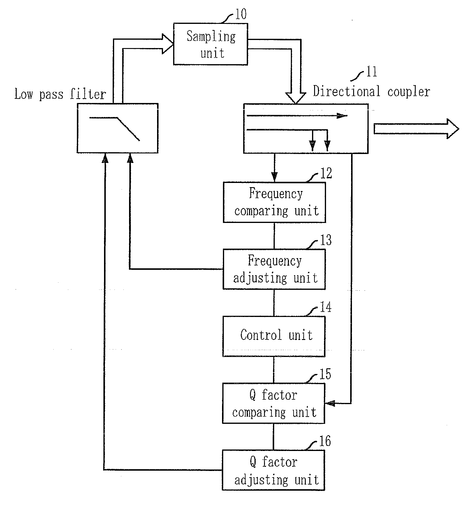
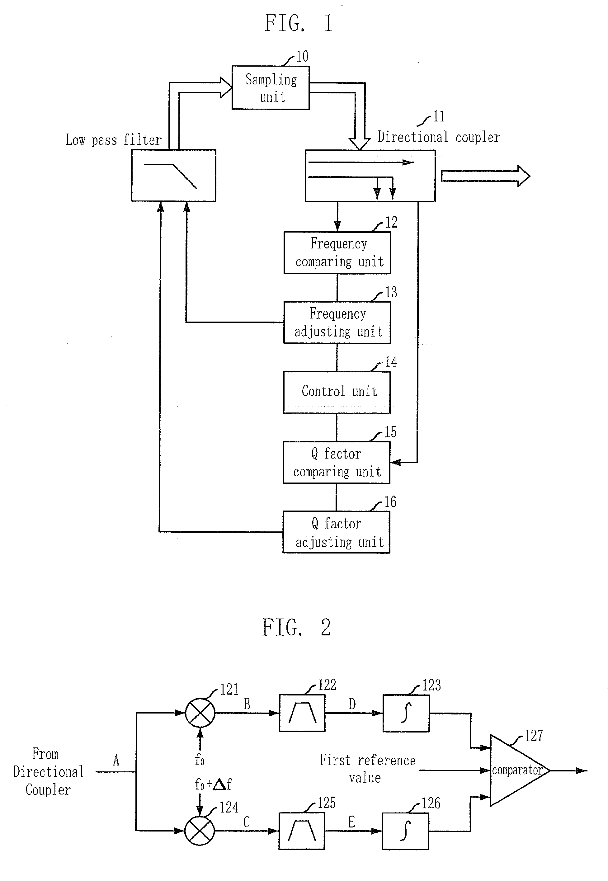
[0030]FIG. 1 is a block diagram illustrating an apparatus for adjusting frequency characteristic and Q factor of a low pass filter in accordance with an embodiment of the present invention.

[0031]As shown in FIG. 1, the apparatus for adjusting the frequency characteristic and the Q factor of the LPF includes a sampling unit 10, a directional coupler 11, a frequency comparing unit 12, a frequency adjusting unit 13, a control unit 14, a Q factor comparing unit 15 and a Q factor adjusting unit 16.

[0032]The sampling unit 10 samples an output signal of the LPF. The directional coupler 11 performs coupling the sampling signal sampled in the sampling unit 10.

[0033]The frequency comparing unit 12 extracts a first frequency band signal by multiplying a first frequency (f0) by the coupled s...


PUM


Abstract

Provided are an apparatus for adjusting frequency characteristic and Q factor of a low pass filter (LPF) and a method thereof. The apparatus includes: a frequency comparing unit for calculating a first square value and a second square value, and comparing a first reference value with the first and the second square values; a frequency adjusting unit for adjusting the frequency characteristic to range the first reference value between the first square value and the second square value; a Q factor comparing unit for calculating a third square value, and comparing a second and a third reference values with the third square value; a control unit for activating the Q factor comparing unit when the frequency characteristic is completely adjusted; and a Q factor adjusting unit for adjusting the Q factor to range the third square value between the second reference value and the third reference value.

Description

CROSS-REFERENCE TO RELATED APPLICATIONS[0001]The present invention claims priority of Korean Patent Application No. 10-2006-0107884, filed on Nov. 2, 2006, which is incorporated herein by reference.BACKGROUND OF THE INVENTION[0002]1. Field of the Invention[0003]The present invention relates to an apparatus for adjusting frequency characteristic and Q factor of a low pass filter and a method thereof; and, more particularly, to an apparatus for adjusting frequency characteristic and Q factor of a low pass filter that can improve filtering efficiency of the low pass filter (LPF) by adjusting the frequency characteristic and the Q factor according to a desired filtering function and a method thereof. The frequency characteristic and the Q factor are changed due to the variation of capacitance and resistance occurring when the LPF is implemented by an application specific integrated circuit (ASIC).[0004]This work was supported by the Information Technology (IT) research and development p...

Claims


Application Information

Patent Timeline
IPC IPC(8): H04B1/10
CPCH03H11/1291H03H7/0153H03H17/00
Inventor LEE, SEUNG-SIKPARK, BONG-HYUKKIM, CHANG-WANCHOI, SANG-SUNG
Owner ELECTRONICS & TELECOMM RES INST
Learn More