Swept turbomachine blade

a turbomachine and blade technology, applied in the direction of machines/engines, mechanical apparatus, liquid fuel engines, etc., can solve the problems of large noise generation, very severe mechanical stress on the blade, and source of noise, so as to reduce noise generation, reduce noise generation, and reduce noise generation

Active Publication Date: 2008-05-08
SN DETUDE & DE CONSTR DE MOTEURS DAVIATION S N E C M A
View PDF6 Cites 46 Cited by
  • Summary
  • Abstract
  • Description
  • Claims
  • Application Information

AI Technical Summary

Benefits of technology

[0005]A main object of the present invention is thus to mitigate such drawbacks by proposing a new shape for a turbomachine blade that enables good aerodynamic operation to be guaranteed under all operating conditions of the turbomachine, while minimizing the noise generated.
[0011]The Applicant has found that the presence of a belly (corresponding to the bottom limit of the intermediate stack) at a height lying in the range 30% to 40% of the total height of the blade, combined with the angles of inclination of the leading edge as defined above serves to improve considerably the aerodynamic performance of the turbomachine, in particular at high power. At high specific flow, this means that there is a large increase in the efficiency of the fan of a turbomachine fitted with such blades. The acoustic characteristics of the blade are also improved. In addition, the blade of the invention satisfies criteria for mechanical balancing and manufacturability using composite material.

Problems solved by technology

Although high flow speeds make it possible in particular to improve the flow rate of the gas so as to increase the thrust of the turbomachine, they nevertheless present the drawback of generating a large amount of noise.
In particular, the “supersonic shockwave” corresponding to the changeover from supersonic speeds to subsonic speeds in the gas flow contributes a major fraction of this noise.
Other interaction phenomena involving the turbulence of the gas flow in the proximity of the fan (broadband noise) also constitute sources of noise.
In particular, at high speeds of rotation, the mechanical stresses to which the blades are subjected are very severe because of the high levels of vibration and because of the centrifugal force that is applied to the blades.
Nevertheless, none of those blades makes it possible to obtain aerodynamic operation that is effective under all conditions of use of the turbomachine, in particular at full power (e.g. during takeoff and at the end of the airplane climbing) and at partial power (e.g. during the approach stage of the airplane), while complying with noise standards that are becoming more and more strict.

Method used


Image

  • Swept turbomachine blade
  • Swept turbomachine blade
  • Swept turbomachine blade

Examples


Embodiment Construction

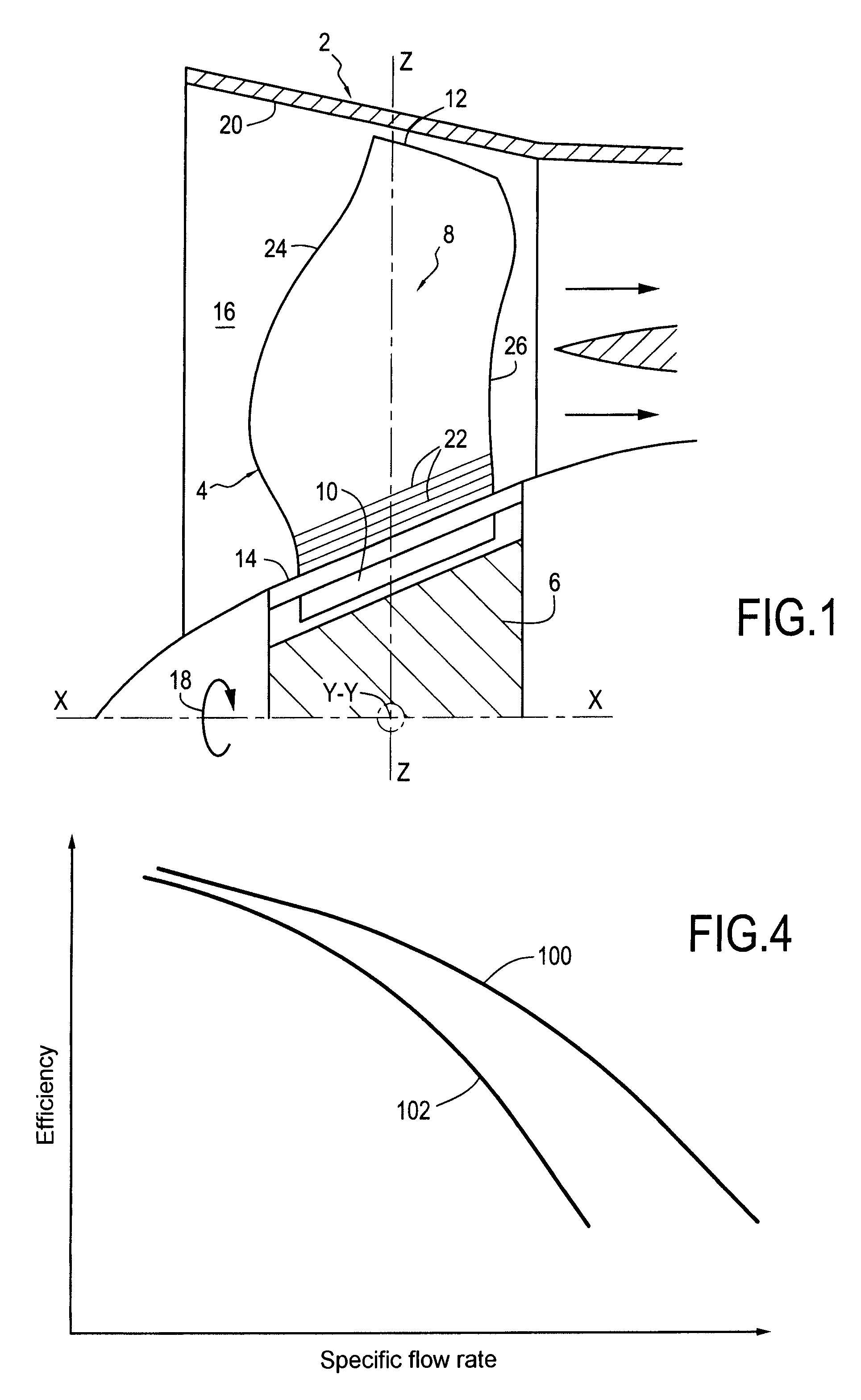
[0021]FIG. 1 is a diagrammatic and fragmentary view of the fan 2 of an aviation turbomachine. It is made up of a plurality of blades 4 that are regularly spaced apart around a disk 6 (or hub) of a rotor centered on a longitudinal axis X-X of the fan.

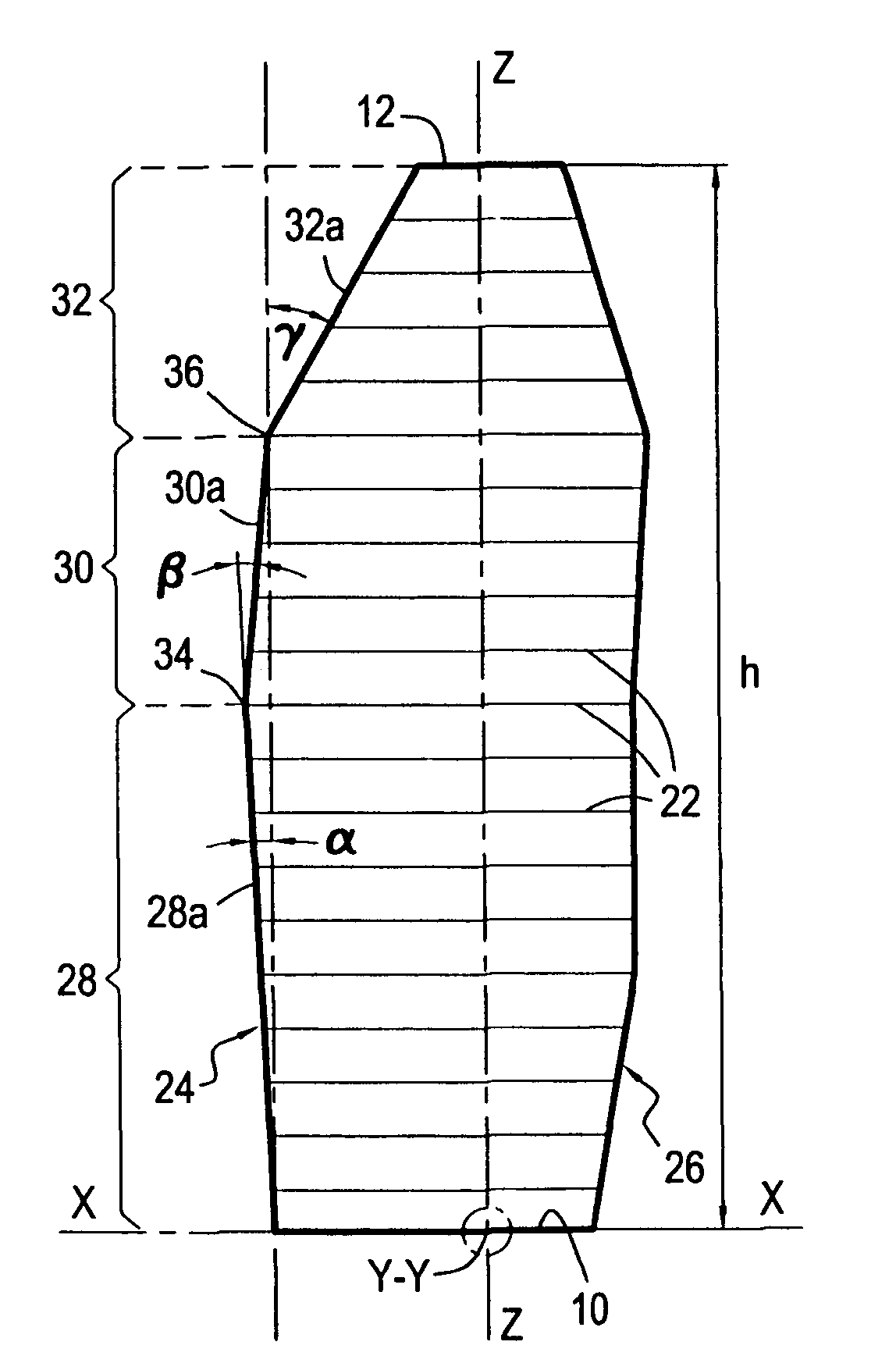
[0022]In known manner, each blade 4 comprises in particular an airfoil 8, a root 10, and a tip 12. The root 10 of the blade is mounted on the rotor disk 6 and is connected to the airfoil 8 via a platform 14 defining the inside of the flow passage 16 of a gas stream passing through the fan. The rotor disk 6 is driven in rotation about the longitudinal axis X-X in the direction marked by arrow 18. The tip 12 of the blade is situated facing the inside face 20 of a stationary annular casing of the fan, said face 20 defining the outside of the passage 16.

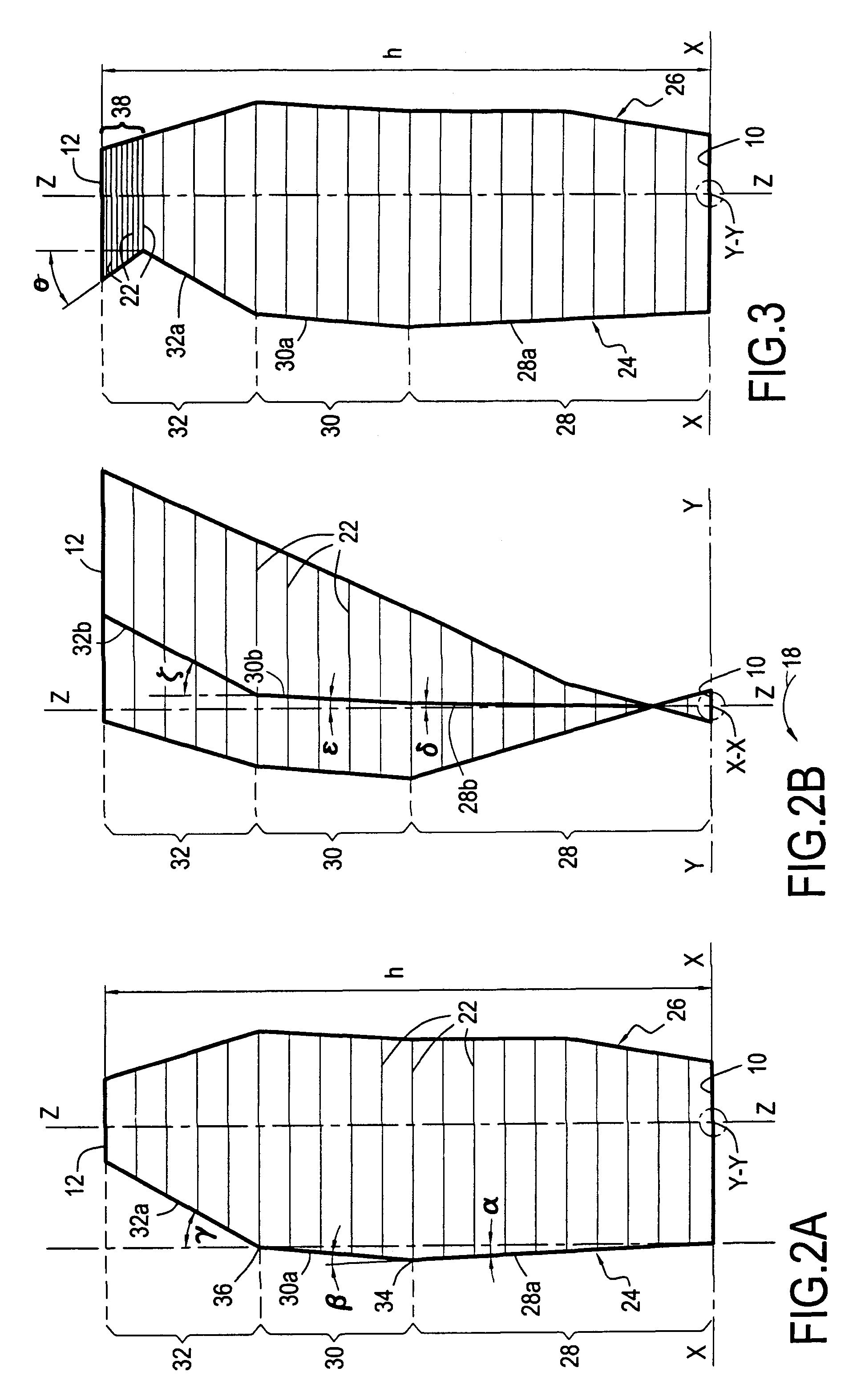
[0023]The airfoil 8 is made up of a plurality of blade sections 22 that are stacked along a radial axis Z-Z perpendicular to the axis X-X. The blade sections 22 are situated at increasing rad...


PUM


Abstract

The invention relates to a turbomachine blade comprising a plurality of blade sections stacked along a radial axis, and in which the projection of a line interconnecting the leading edges of the blade sections of the bottom stack onto a mid-plane presents a first longitudinal angle of inclination towards the leading edge that lies in the range 10° to 25°, the projection of a line interconnecting the leading edges of the blade sections of the intermediate stack presents a second longitudinal angle of inclination towards the trailing edge lying in the range 10° to 25°, the projection of a line interconnecting the leading edges of the blade sections of the top stack presents a third longitudinal angle of inclination towards the trailing edge lying in the range 20° to 50°, and the bottom limit of the intermediate stack of the blade sections lies in the range 30% to 40% of the total radial height of the stack of blade sections.

Description

BACKGROUND OF THE INVENTION [0001]The present invention relates to the general field of moving blades for turbomachines such as the blades for the fan of a turbomachine.[0002]The fan blades of a turbomachine are subjected to speeds of rotation that can impart subsonic to supersonic speeds to the gas flow passing through the fan. Although high flow speeds make it possible in particular to improve the flow rate of the gas so as to increase the thrust of the turbomachine, they nevertheless present the drawback of generating a large amount of noise. In particular, the “supersonic shockwave” corresponding to the changeover from supersonic speeds to subsonic speeds in the gas flow contributes a major fraction of this noise. Other interaction phenomena involving the turbulence of the gas flow in the proximity of the fan (broadband noise) also constitute sources of noise.[0003]Engine manufacturers therefore seek to design fan blades that enable thrust to be increased, while minimizing the n...

Claims


Application Information

Patent Timeline
Patent Type & Authority Applications(United States)
IPC IPC(8): F01D5/14
CPCF01D5/141F04D29/324F04D29/384F05D2240/301Y02T50/672Y02T50/673F04D29/681F05D2250/70Y02T50/60
Inventor BOIS, BEATRICE NATHALIEMADEC, ALAIN PAULM'BENGUE, AMADOU LAMINE
Owner SN DETUDE & DE CONSTR DE MOTEURS DAVIATION S N E C M A
Why Eureka
Try Eureka