Systems, methods and devices for removing obstructions from a blood vessel

a technology of obstruction and blood vessel, applied in the field of methods and devices for removing obstructions from blood vessels, can solve the problems that the interaction between the balloon catheter and the leading edge of the catheter may tend to shear off portions of the obstruction, and achieve the effects of reducing the likelihood of the obstruction, and reducing the risk of obstruction

Inactive Publication Date: 2008-05-08
STRYKER CORP
View PDF3 Cites 122 Cited by
  • Summary
  • Abstract
  • Description
  • Claims
  • Application Information

AI Technical Summary

Benefits of technology

[0007] In another aspect of the present invention, another obstruction removal device is provided which has at least one closed loop and preferably two closed loops. The closed loop provides an advantage when advanced through a catheter or sheath in that the closed loop produces opposing radial forces on the catheter or sheath through which the loop is advanced. In this manner, the obstruction removal device can be advanced more easily through the catheter or sheath to prevent binding or kinking of the device during advancement. In a preferred embodiment, the obstruction removal device has two loops of varying diameter with the distal loop having a larger diameter. Each of the loops lie in a plane with the planes of the two loops preferably being perpendicular to one another.
[0008] In another aspect of the invention, another obstruction removal device is provided which has wound sections formed by one or more filaments which are separated by sections substantially free of the filaments. The intermittent wound sections provide discrete portions where the obstruction can be engaged. In an embodiment, the wound sections can slide on the core element to provide flexibility when advancing the obstruction removal device. The wound sections and sections free of filament are preferably about 1-5 mm long. The obstruction removal device preferably has at least three wound sections and more preferably at least five wound sections.
[0009] In still another aspect of the invention, another obstruction removal device is provided which has alternating large and small diameter portions. In a preferred embodiment, the obstruction removal device has at least four large diameter sections and three smaller diameter portions. The alternating large and small diameter portions may help to engage certain types of obstructions and can also help to prevent parts of the obstruction from breaking off and migrating downstream.
[0011] The devices of the present invention may be manufactured in any suitable manner. In another aspect of the present invention, the obstruction removal device has a core element surrounded by a sheath. A strand, preferably about four strands, are positioned between the core element and the tube. The strand and the tube prevent any part of the obstruction removal device from breaking free should the core element fail. The strand and tube will hold the obstruction removal device together even if the core element breaks. The sheath is preferably flexible so that the sheath can undergo much larger deflections than the core element.
[0012] The obstruction removal devices of the present invention may also be advanced through a guide catheter having a flow restricting element which is preferably a balloon but may be any other suitable structure. The flow restricting element is expanded to reduce blood flow through the obstructed vessel to minimize the likelihood that the obstruction will migrate downstream.
[0013] In another aspect of the invention, a system is provided which has an expandable capture element and an obstruction engaging device which together work to remove an obstruction from a blood vessel. The capture element is advanced through the patient in a collapsed position and is expanded when at the desired location. The obstruction engaging device preferably has one or more filaments which provide a relatively flexible interaction between the engaging device and the capture element. This provides advantages over the use of a balloon catheter as described in greater detail below. The obstruction engaging device preferably has 1-4 filaments and more preferably 1-2 filaments. Of course, the obstruction engaging device may have more filaments without departing from various aspects of the invention and, in fact, the device may form a filter which further helps to prevent portions of the obstruction from being carried downstream.

Problems solved by technology

A problem with the system of U.S. Pat. No. 5,102,415 is that the interaction between the balloon catheter and the leading edge of the catheter may tend to shear off portions of the obstruction.
This can cause obvious problems when working in sensitive vascular areas.

Method used


Image

  • Systems, methods and devices for removing obstructions from a blood vessel
  • Systems, methods and devices for removing obstructions from a blood vessel
  • Systems, methods and devices for removing obstructions from a blood vessel

Examples


Embodiment Construction

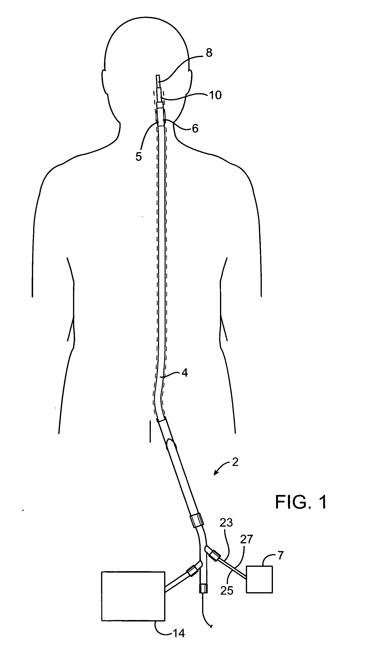
[0081] Referring now to FIGS. 1-4, a system 2 for removing an obstruction is shown. A guide catheter 4 is advanced to a location proximal to an obstruction. When accessing the cerebral vasculature, for example, the guide catheter 4 is often positioned in the carotid or vertebral artery. Of course, the guide catheter 4 may not be necessary or may be positioned in any other suitable location depending upon the location of the obstruction. The guide catheter 4 preferably has a flow restricting element 6 which restricts or even stops blood flow through the vessel as described below. The flow restricting element 6 is preferably a balloon 5 coupled to a source of inflation fluid 7 which is used to inflate the balloon 5.

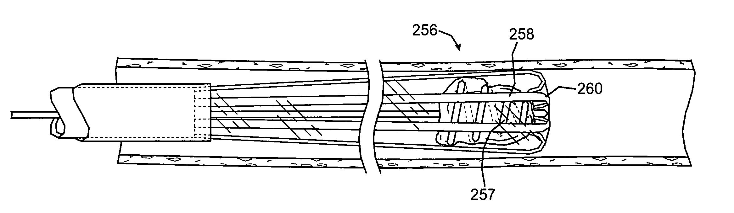
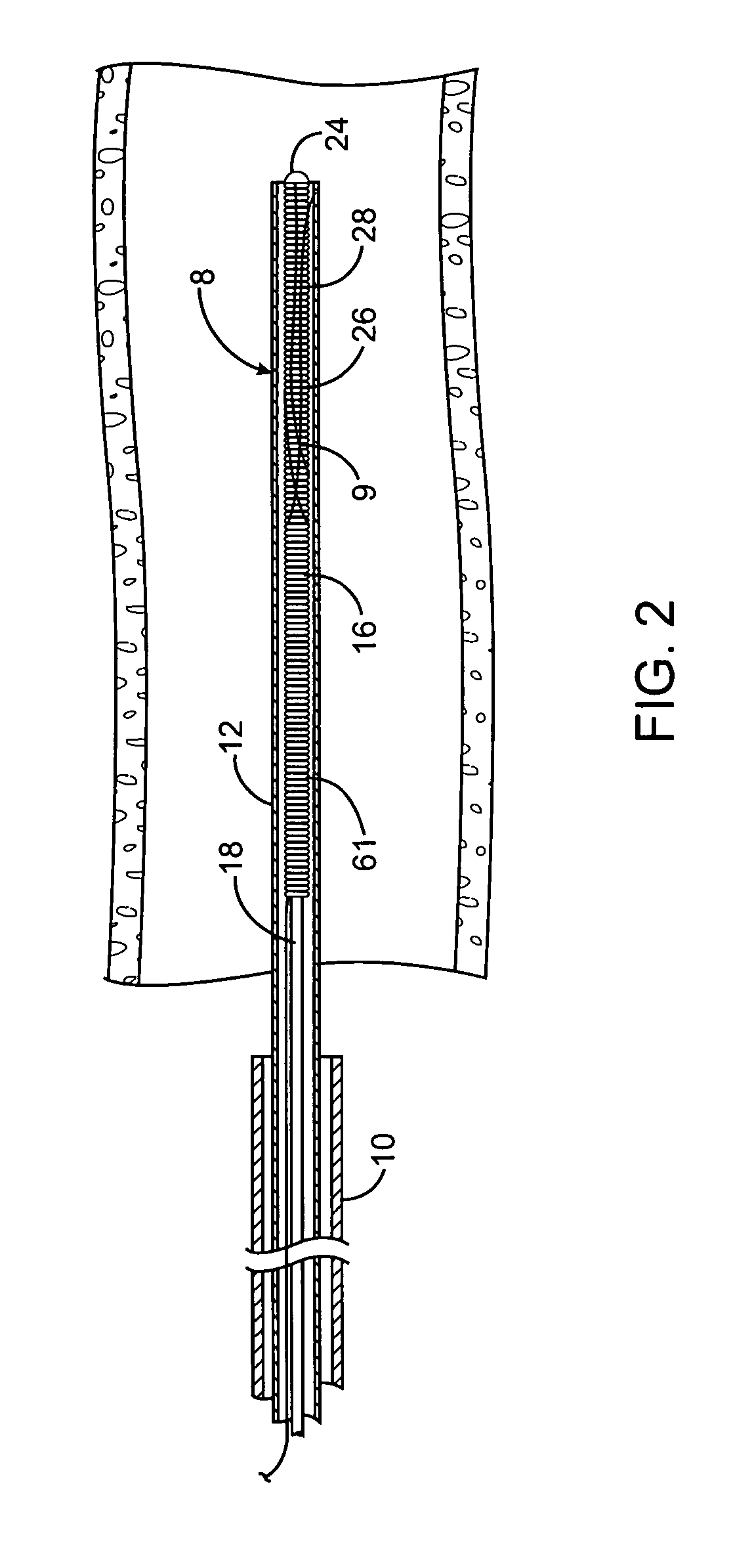
[0082] An obstruction removing device 8 is advanced through the guide catheter 4 to the obstruction. A microcatheter 10 may also be positioned within the guide catheter 4 to deliver the obstruction removing device 8 further into the vasculature. The obstruction removing de...


PUM


Abstract

A system for removing an obstruction from a blood vessel includes an obstruction engaging element and an expandable capture element. The capture element preferably has a flexible cover and an expandable support structure. The engaging element engages the obstruction and moves the obstruction into the capture element. The capture element protects the obstruction when the obstruction is moved into the catheter.

Description

CROSS-REFERENCE TO RELATED APPLICATIONS [0001] The present application is a continuation in part of Ser. No. 09 / 756,476, filed Jan. 8, 2001, which is a continuation-in-part of application Ser. No. 09 / 605,143, filed Jun. 29, 2000, entitled, “Methods and Devices for Removing an Obstruction From a Blood Vessel,” by inventors Sepetka, et al., the full disclosures of which are incorporated herein by reference for all purposes.BACKGROUND OF THE INVENTION [0002] The present invention is directed to methods and devices for removing obstructions from blood vessels. The device may be used to retrieve and remove clots and other biological obstructions. The device may also be used to retrieve embolic coils and the like which have been misplaced or have migrated to an undesirable location. [0003] One such obstruction removal device is disclosed in U.S. Pat. No. 5,895,398 which is hereby incorporated by reference. The device has an expandable engaging member which is introduced into the blood ves...

Claims


Application Information

Patent Timeline
Patent Type & Authority Applications(United States)
IPC IPC(8): A61M29/00A61B17/22A61M25/00
CPCA61B17/22031A61F2230/0091A61B18/1492A61B2017/22034A61B2017/2212A61B2017/2215A61B2017/2217A61B2018/00214A61B2018/00898A61F2/013A61M25/0068A61M25/0074A61M25/008A61M25/0082A61F2002/016A61F2002/018A61B17/221
Inventor SEPETKA, IVANDIECK, MARTINGIA, SONMILLER, JOHNNGO, TIFFANY TRANPIERCE, RYAN
Owner STRYKER CORP
Why Eureka
Try Eureka