Method of controlling landing strings in offshore operations

Inactive Publication Date: 2008-05-15
DEEPBLUE TECH L L C
View PDF11 Cites 59 Cited by
  • Summary
  • Abstract
  • Description
  • Claims
  • Application Information

AI Technical Summary

Benefits of technology

[0008]Also disclosed is a method of operating and/or monitoring temporarily installed equipment through a tubing hanger. The tubing hanger is operatively associated with a subsea production tree. The method includes delivering hydraulic or electrical controls from a vessel through a control system umbilical, and terminating at a junction plate mated to the subsea production tree. The production tree provides internal conduits communicating controls through a series of stabs. The control of the tubing hanger and other equipment is established by landing the completion within the production tree, which has the effect of enabling the stabs and establishing communications with the completion equipment, and wherein the completion equipment is typically surface controlled sub-surface valves (SCSSV), electrical gauges and chemical injection mandrels. The method further includes reconfiguring and adding stabs which diverts controls up the assembly into the tubing hanger running tool and ultimately to other equipment. By establishing communication and control in this way, full functional control of the devices is provided. In order to maintain status of any unlatched elements of the system during disconnect activities the disconnection points will require hydraulic checking stabs, these will trap hydraulic pressure allowing the latch to reconnect and re-establish communications. This method of control requires that during the initial deployment prior to landing the tubing hanger, the oper

Problems solved by technology

As those of ordinary skill in the art will readily appreciate, when wells are drilled and completed to subterranean reservoirs, the well will experience significant pressures which require containment

Method used


Image

  • Method of controlling landing strings in offshore operations
  • Method of controlling landing strings in offshore operations
  • Method of controlling landing strings in offshore operations

Examples


Embodiment Construction

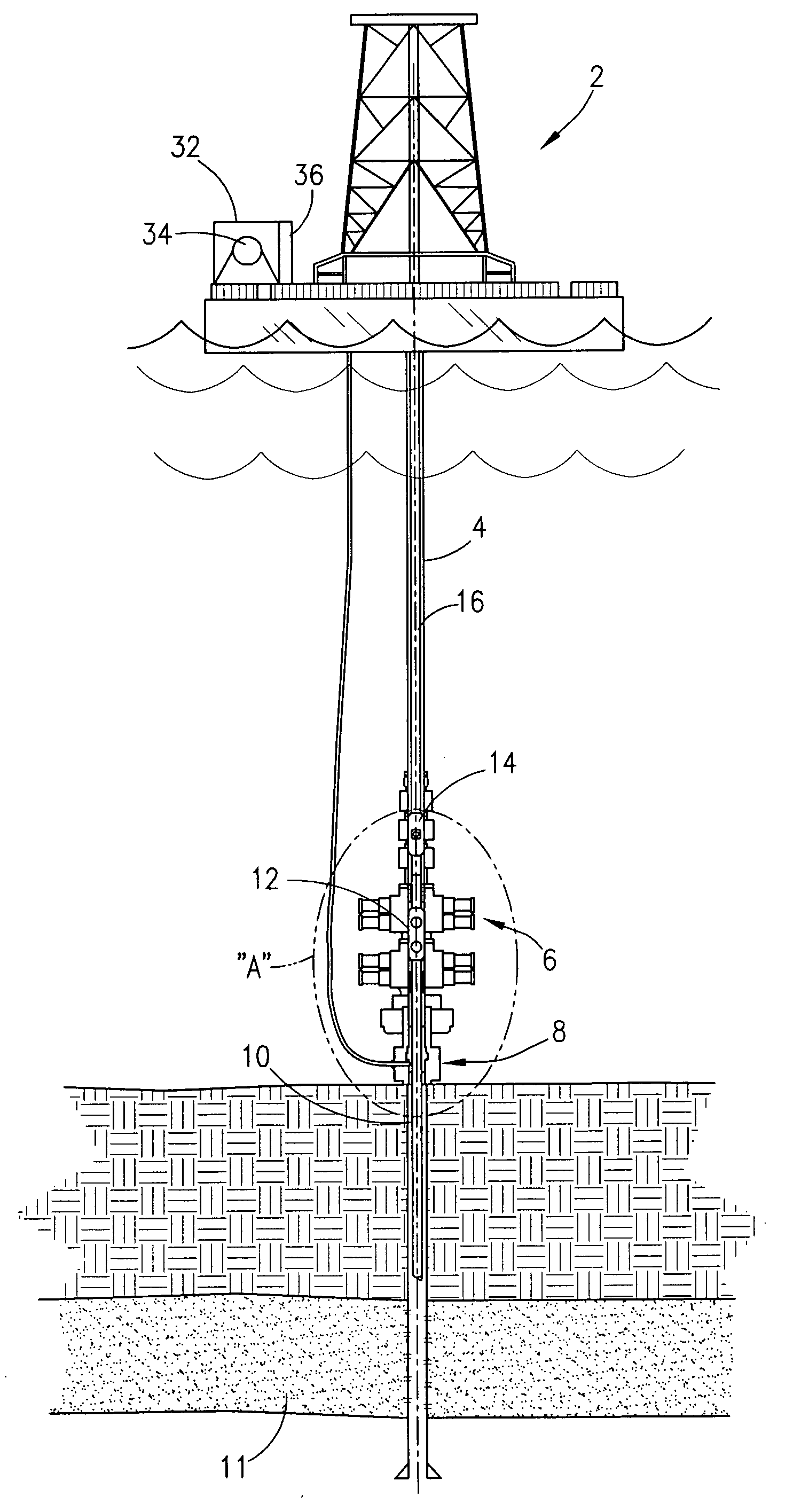
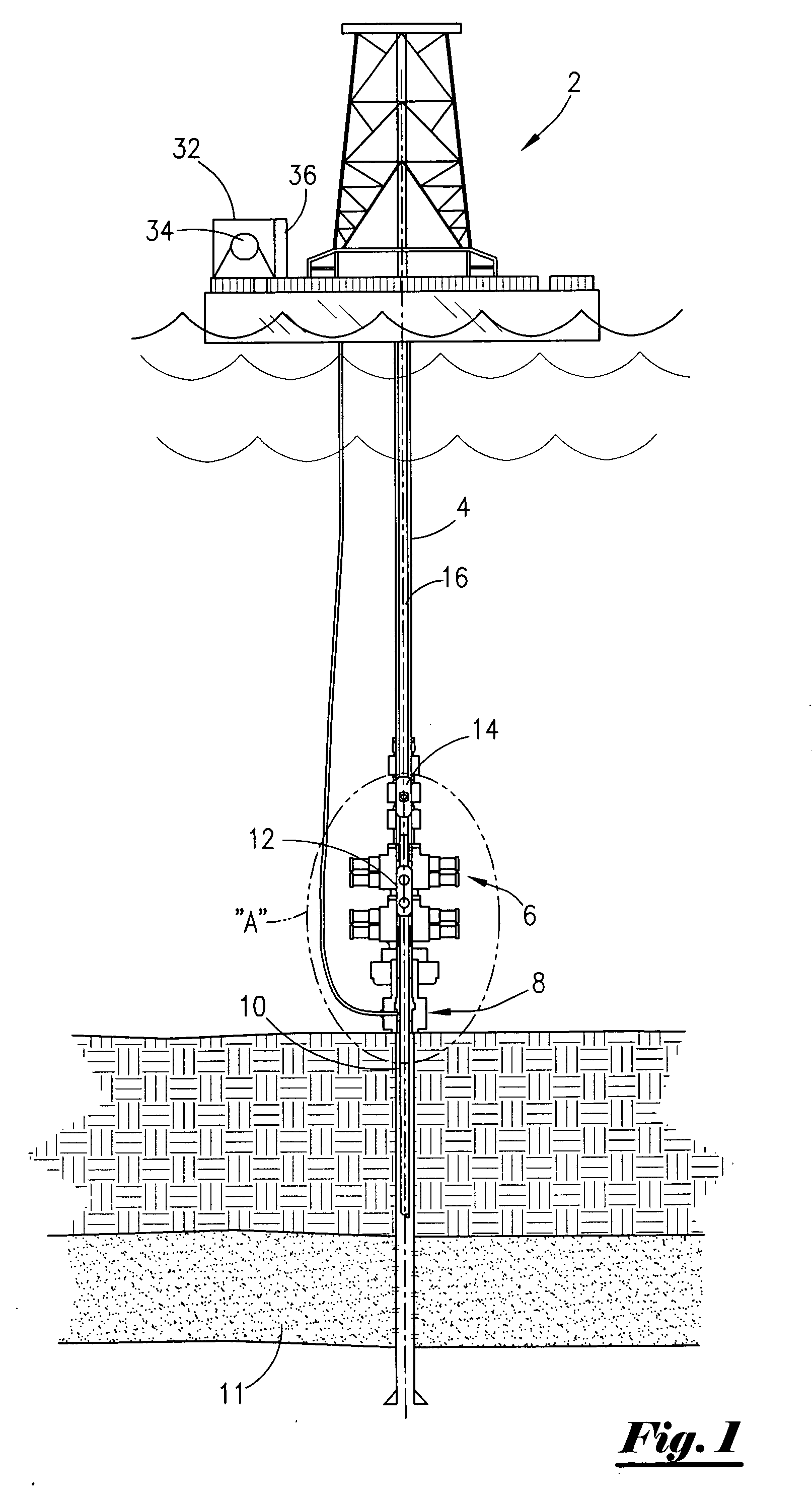
[0013]Referring now to FIG. 1, a well bore schematic of the preferred embodiment of the present system will now be described. As can be seen, a floating platform 2, such as a semi-submersible drilling vessel, is positioned over a well. It should be noted that the platform 2 may be an offshore floating platform, an anchored vessel, or even a jack-up type of platform. A marine riser 4 extends from the floating platform 2. The marine riser 4 is operatively connected to a subsea blow-out preventor system (BOP system), wherein the bop system is seen generally at 6. The BOP system 6 is made up of individual BOP components as will be more fully set later in the description. The BOP system 6 will be operatively connected to subsea production tree 8, and wherein the production tree 8 will in turn be operatively connected to the subterranean well 10. The subsea production tree 8 is adjacent the sea bed. As very well understood by those of ordinary skill in the art, the subterranean well 10 ma...


PUM


Abstract

A method and system of operating a landing string utilized on a floating platform. The landing string is disposed within a marine riser, with the marine riser being connected to a subsea production tree, and wherein the subsea production tree contains internal conduits communicating controls through a series of stab passageways. The method comprises providing a tubing hanger operatively connected to the landing string, delivering hydraulic or electrical controls from the floating platform through a control system umbilical to a junction plate operatively attached to the subsea production tree. The method further comprises landing the tubing hanger into the subsea production tree, establishing control of the tubing hanger by providing the hydraulic controls to the tubing hanger with the series of stab passageways through the subsea production tree, and establishing control of the completion bottom hole assembly with the stab passageways. In the preferred embodiment, the landing string has attached thereto a completion bottom hole assembly that will be placed in the well.

Description

[0001]This application is a Continuation-in-Part Application of my co-pending provisional application Ser. No. 60 / 826,289, filed on 20 Sep. 2006 by Inventor Ross Trewhella, and entitled “Method of Functioning and / or Monitoring Temporarily Installed Equipment Through a Tubing Hanger”.BACKGROUND OF THE INVENTION[0002]This invention relates to a method of controlling equipment in offshore operations. More specifically, but without limitations, this invention relates to a system and method of landing and locking completions and other bottom hole assemblies with a landing string from a semi-submersible or dynamically positioned drilling vessel, wherein the landing string contains well control equipment.[0003]In the drilling and completion of wells located in bodies of water, operators find it necessary to incorporate safety measures. As those of ordinary skill in the art will readily appreciate, when wells are drilled and completed to subterranean reservoirs, the well will experience sig...

Claims


Application Information

Patent Timeline
IPC IPC(8): E21B7/128
CPCE21B33/04E21B33/038
Inventor TREWHELLA, ROSS JOHN
Owner DEEPBLUE TECH L L C
Why Eureka
Try Eureka