Electric Direct-Acting Actuator and Electric Brake Device

a direct-acting actuator and brake device technology, which is applied in mechanical devices, transportation and packaging, gearing, etc., can solve the problems of insufficient linear motion, inability to achieve such a large power increasing function as required in electric brake devices, and difficulty in reducing the size of electric direct-acting actuators. , to achieve the effect of reducing the size of the electric direct-acting actuator, forming easily, and reducing the cos

Inactive Publication Date: 2008-05-15
NTN CORP
View PDF11 Cites 38 Cited by
  • Summary
  • Abstract
  • Description
  • Claims
  • Application Information

AI Technical Summary

Benefits of technology

[0012]The helical rib may be defined by a rib member engaged in a helical groove formed in the radially outer surface of the rotor shaft or the radially inner surface of the outer ring member. With this arrangement, the helical rib can be formed easily at a low cost.
[0013]By transmitting the linear motion of the planetary rollers to the object to be driven through thrust bearings for supporting the rotation of the respective planetary rollers about their own axes and a thrust bearing for supporting the rotation of the planetary rollers about the rotor shaft, it is possible to transmit the linear motion of the planetary rollers, which rotate about their own axes while rotating about the rotor shaft, to the object to be driven without loss.
[0015]For the electric direct-acting actuator according to this invention, because a plurality of planetary rollers are provided between the radially outer surface of the rotor shaft of the electric motor and the radially inner surface of an outer ring member fixed in position around the rotor shaft, whereby the planetary rollers are configured to rotate about the rotor shaft while rotating about their own axes when the rotor shaft rotates, and a relatively axially moving means is provided between the respective planetary rollers and one of the rotor shaft and the outer ring member for axially and relatively moving the planetary rollers, whereby the rotary motion of the rotor shaft is converted to a linear motion of the planetary rollers, it is possible to obtain a large power increasing function without mounting a separate speed reducer. Also, because the planetary rollers are brought into rolling contact with the rotor shaft and the outer ring member on large areas, even if vibrations are applied thereto, motion can be stably converted and transmitted.
[0016]By forming the relatively axially moving means from a helical rib provided on the radially outer surface of the rotor shaft or the radially inner surface of the outer ring member, and circumferential grooves formed in the radially outer surface of each of the planetary rollers, the circumferential grooves being arranged at the same pitch as the turns of the helical rib, the helical rib being engaged in the circumferential grooves, whereby when the planetary rollers rotate about the rotor shaft while rotating about their own axes, the planetary rollers are relatively and axially moved, it is possible to further increase the power increasing function.
[0019]Because one of the above-described electric direct-acting actuators is used in the electric brake device according to this invention, it is not necessary to mount a separate speed reducer, so that it is possible to compactly design the brake device while maintaining a large power increasing function, and also improve the durability even if used in an environment where vibrations are applied from the road surface.

Problems solved by technology

Ball-screw mechanisms and ball-ramp mechanisms used in conventional electric direct-acting actuators as described above has a power increasing function to a certain extent due to their motion converter for converting the rotary motion along threads having a lead or inclined cam surfaces, but cannot achieve such a large power increasing function as required in e.g. electric brake devices.
If the inclination angle of the cam surfaces of the ball-ramp mechanism is reduced, the stroke of the linear motion will be insufficient.
By mounting a gear speed reducer such as a planetary gear speed reducer, it becomes difficult to reduce the size of the electric direct-acting actuator.
Further, because the gears of the gear speed reducer mesh with each other on small contact areas, if such a gear speed reducer is mounted in an area where it is influenced by vibrations from the road surfaces as in the case of an electric brake device, the gears tend to become damaged.

Method used


Image

  • Electric Direct-Acting Actuator and Electric Brake Device
  • Electric Direct-Acting Actuator and Electric Brake Device
  • Electric Direct-Acting Actuator and Electric Brake Device

Examples


Embodiment Construction

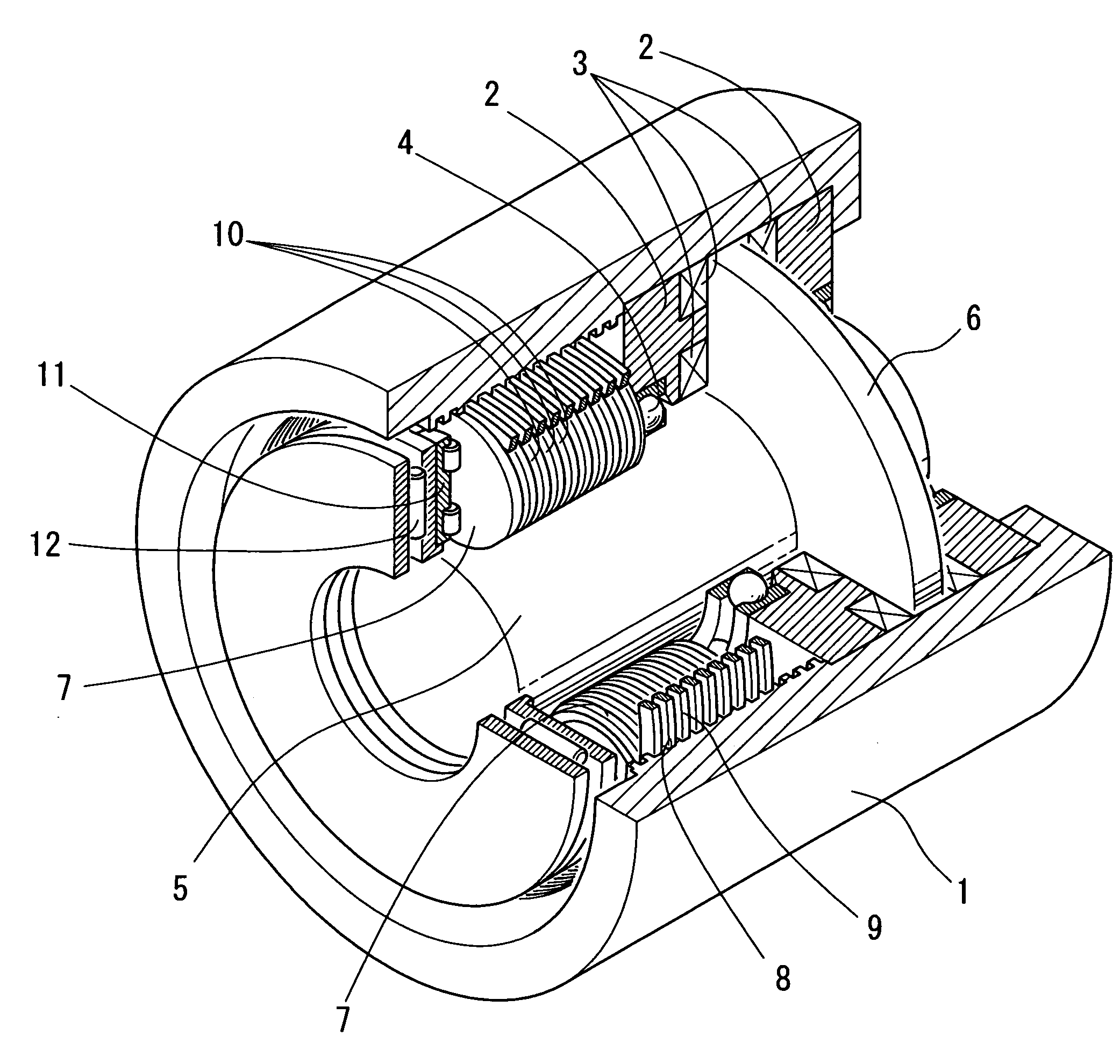
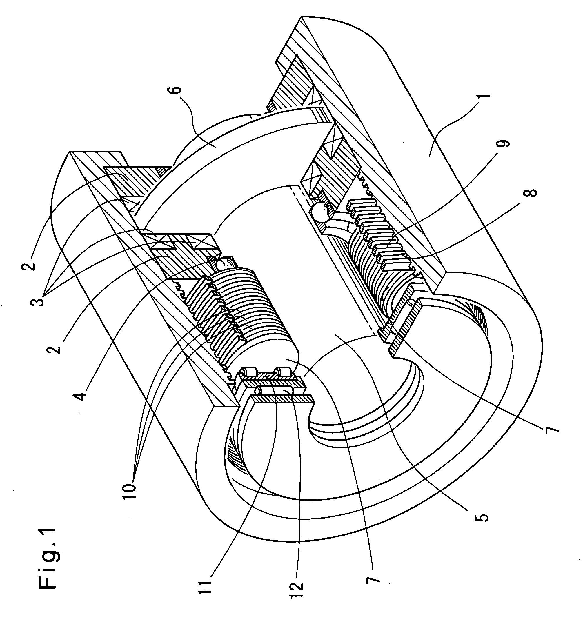
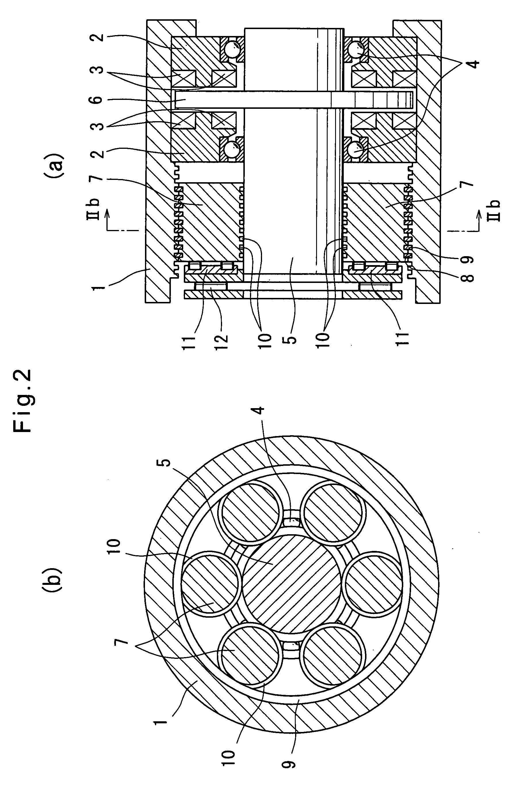
[0041]Now the embodiments of the present invention are described with reference to the drawings. FIGS. 1, 2(a) and 2(b) show an electric direct-acting actuator of the first embodiment. This electric direct-acting actuator includes a pair of stator cores 2 received in an outer ring member 1 at one end thereof. Coils 3 of a multipolar electric motor are fixed to the stator cores 2 so as to axially oppose each other. A rotor 6 mounted on a rotor shaft 5 supported by the stator cores 2 through ball bearings 4 rotates between the opposed stators. At the other end of the outer ring member 1, a plurality of planetary rollers 7 are disposed between the radially inner surface of the outer ring member 1 and the radially outer surface of the rotor shaft 5 with a negative clearance. As the rotor shaft 5 rotates, the planetary rollers 7 rotate about the rotor shaft 5 while simultaneously rotating about their own axes. To increase wear resistance, surface hardening treatment is applied to the rad...


PUM


Abstract

An electric direct-acting actuator is proposed which can maintain a large power increasing function without mounting a separate speed reducer.
A plurality of planetary rollers 7 are disposed between the radially outer surface of a rotor shaft 5 of an electric motor and the radially inner surface of an outer ring member 1 fixed in position around the rotor shaft 5 so as to be rotatable about the rotor shaft 5 and about their own axes when the rotor shaft 5 rotates. A helical rib is defined by a rib member 9 engaged in a helical groove 8 formed in the radially inner surface of the outer ring member 1. The helical rib is engaged in circumferential grooves 10 formed in the radially outer surface of each planetary roller 7 at the same pitch as the turns of the helical rib. Thus, the rotary motion of the rotor shaft 5 is converted to a linear motion of the planetary rollers 7, so that it is possible to ensure a large power increasing function without mounting a separate speed reducer.

Description

TECHNICAL FIELD[0001]The present invention relates to an electric direct-acting actuator for converting the rotary motion of an electric motor to a linear motion to linearly drive an object to be driven, and an electric brake device which uses an electric direct-acting actuator to press a braking member against a member to be braked.BACKGROUND ART[0002]Electric direct-acting actuators for converting the rotary motion of an electric motor to a linear motion to linearly drive an object to be driven typically include ball-screw mechanisms or ball-ramp mechanisms for such motion conversion. Also, in order to obtain a large linear driving force with a small-capacity electric motor, such actuators typically include a gear speed reducer such as a planetary gear speed reducer (as disclosed e.g. in Patent document 1).[0003]On the other hand, although many of today's vehicle brake devices are of the hydraulic type, electric brake devices are gathering attention now because they can perform so...

Claims


Application Information

Patent Timeline
Patent Type & Authority Applications(United States)
IPC IPC(8): F16H25/18B60L7/00
CPCF16D65/18F16D2121/24Y10T74/18568F16H25/2252H02K7/06F16D2125/405F16H25/2427H02K7/102H02K21/24
Inventor NAKAZEKI, TSUGITO
Owner NTN CORP
Why Eureka
Try Eureka