Light-emitting module of vehicular lamp

Inactive Publication Date: 2008-05-15
KOITO MFG CO LTD
View PDF10 Cites 17 Cited by
  • Summary
  • Abstract
  • Description
  • Claims
  • Application Information

AI Technical Summary

Benefits of technology

[0008]One or more embodiments of the present invention enable formation of a cutoff line without requiring a shade and reduce unevenness in light distribution.
[0009]A light-emitting module of a vehicular lamp according to one or more embodiments of the present invention is a light-emitting module that includes a semiconductor light-emitting element with a generally oblong shape, and a planar electrode formed on a surface of the semiconductor light-emitting element, wherein the planar electrode has a generally right triangular electrode portion that is defined by an oblique cut-off line on any one of four corners of the semiconductor light-emitting element, and is formed with a wire bonding portion that establishes a current-carrying connection with the generally right tri

Problems solved by technology

Accordingly, if a plurality of light-emitting modules are used to form a light distribution pattern, then there is uneven brightness around the bound

Method used


Image

  • Light-emitting module of vehicular lamp
  • Light-emitting module of vehicular lamp
  • Light-emitting module of vehicular lamp

Examples


Embodiment Construction

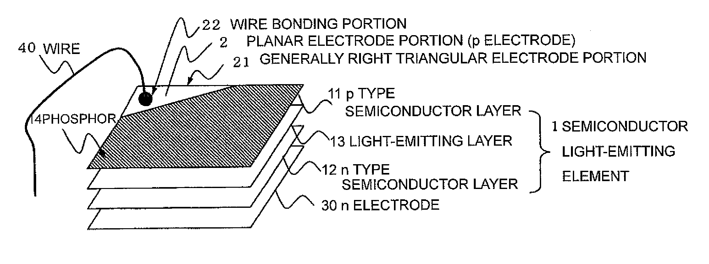
[0023]FIG. 1 is a drawing showing the structure of a light-emitting module of a vehicular lamp according to one or more embodiments of the present invention. The light-emitting module is mainly structured from a semiconductor light-emitting element 1, and a planar electrode 2 formed on a surface of the semiconductor light-emitting element 1. The semiconductor light-emitting element 1 is an element wherein a p-type semiconductor layer 11 and an n-type semiconductor layer 12 are joined, and includes a light-emitting layer 13 on a bonded interface thereof. The planar electrode 2 is a p-electrode, and has a generally right triangular electrode portion 21 that includes one corner on the oblong-shaped semiconductor light-emitting element 1, as shown in FIG. 1. The generally right triangular electrode portion 21 and a wire 40 are joined and connected to carry current by a wire bonding portion 22 within the planar electrode 2. An n-electrode 30 is formed on a surface opposite the semiconduc...


PUM


Abstract

A light-emitting module includes a semiconductor light-emitting element with a generally oblong shape, and a planar electrode formed on a surface of the semiconductor light-emitting element. The planar electrode has a generally right triangular electrode portion that is defined by an oblique cut-off line on any one of four corners of the semiconductor light-emitting element. The planar electrode is formed with a wire bonding portion that establishes a current-carrying connection with the generally right triangular electrode portion.

Description

BACKGROUND OF INVENTION[0001]1. Field of the Invention[0002]The present invention relates to a light-emitting module of a vehicular lamp that uses a semiconductor light-emitting element such as an LED as a light source.[0003]2. Background Art[0004]There are an increasing number of cases in recent years where a vehicular lamp that includes a headlamp is mounted with a semiconductor light-emitting element (LED) that is compact, lightweight, and has excellent light-emitting efficiency (see Patent Document 1 for an example). A light-emitting surface of an LED chip used as the light source normally has a generally oblong shape, and projecting light from such a light source to form a low beam may necessitate using a shade in order to generate a 15° (or 45°) cut-off line. However, using the shade to block light means that a certain quantity of light is wasted.[0005][Patent Document 1][0006]Japanese Patent Application Publication No. JP-A-2005-85548, pages 4 to 25, FIG. 7.SUMMARY OF INVENTI...

Claims


Application Information

Patent Timeline
IPC IPC(8): H01L33/00F21V9/08F21V17/00H01L33/38H01L33/50H01L33/58
CPCF21S48/10H01L33/38F21Y2105/00F21S41/141F21W2102/135F21W2102/155H01L2224/48463
Inventor ISHIDA, HIROYUKITOKIDA, TSUKASA
Owner KOITO MFG CO LTD
Why Eureka
Try Eureka