Optical Disk Recording Apparatus and Optical Disk Recording Method

a technology of optical disk and recording apparatus, which is applied in the field of optical disk recording apparatus, can solve the problems that the configuration of conventional apparatuses and the open patent application cannot appropriately evaluate the record quality by the learning record, so as to reduce the generation of waiting time, reduce heat generation, and increase the load on the motor

Inactive Publication Date: 2008-05-15
HITACHI CONSUMER ELECTRONICS CORP
View PDF6 Cites 11 Cited by
  • Summary
  • Abstract
  • Description
  • Claims
  • Application Information

AI Technical Summary

Benefits of technology

[0012]With the present invention, it becomes possible to evaluate the record quality in a more stable manner and to adjust the record parameter using the same. This enables reducing heat generation which is caused by an increased load on a motor which changes velocity during reproduction and reducing the generation of a waiting time before the rotation is set when changing the velocity, thus making it possible to implement highly reliable high-speed recording parameter learning processing that reproduces data with the same velocity as that of recording data, and high-speed record verification operation processing.

Problems solved by technology

In other words, the record quality evaluation methods described in the above Japanese Laid-open Patent Applications 2003-006864, and 2005-339690 can not determine that the record quality is low, and thereby there arises a problem that the methods described in the above Japanese Laid-open Patent Applications can not appropriately evaluate the record quality by the learning record.
However, there is also a problem during the verification operation that while the signal recording velocity has to be equalized to the signal reproducing velocity due to the same reason as that described above, the configuration of conventional apparatuses can not appropriately evaluate the record quality.

Method used


Image

  • Optical Disk Recording Apparatus and Optical Disk Recording Method
  • Optical Disk Recording Apparatus and Optical Disk Recording Method
  • Optical Disk Recording Apparatus and Optical Disk Recording Method

Examples


embodiment 1

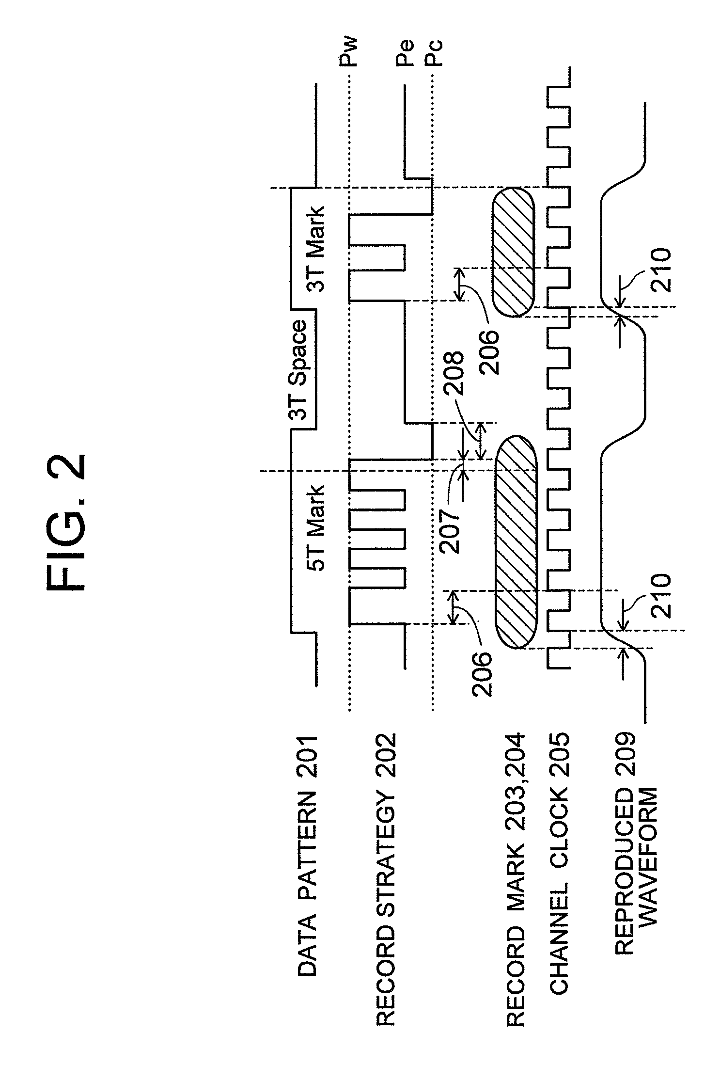
[0031]The record strategy will be described with reference to FIG. 2 and FIG. 3.

[0032]FIG. 2 is a diagram showing an example of a laser drive waveform for recording information on the optical disk and an example of mask formation. 201 is a recording data pattern (hereinafter referred to “record data”), which is illustrated by an NRZI signal here. 202 is a record strategy for recording the record data. This record strategy allows marks (203, 204) and a space therebetween to be formed on a recording film of the optical disk. 205 is a channel clock for controlling the recording or reproduction, while 209 is a waveform reproduced from the marks 203, 204.

[0033]Optimum laser power and optimum timing for recording marks on the optical disk differ depending on the kind of optical disks or combined conditions of the optical disks. The kind of optical disks includes CD-R, CD-RW, DVD-R, DVD-RW, DVD-RAM, DVD+R, DVD+RW, BD-R, BD-RE, HD DVD-R, HD DVD-RW, HD DVD-RAM, and the like. The condition of...

embodiment 2

[0057]Next, the operation of the optical disk apparatus according to an embodiment 2 of the present invention will be described.

[0058]In the embodiment 1, a method is described in which a tap coefficient value is fixed to a coefficient value that satisfies, for example, PR (1, 2, 2, 1) at step 1501 in FIG. 8. However, the adaptive equalization circuit learns the tap coefficient depending the reproduced signals from the pickup head, the coefficient that satisfies the PR (1, 2, 2, 1) is sometimes not an optimum equalization value when the characteristics of the reproduced signal are different from those of the PR (1, 2, 2, 1). A flowchart is shown in FIG. 10 that shows the flow of processing for obtaining the optimum tap coefficient of the adaptive equalization circuit to implement the record strategy learning in such a case. In FIG. 10, same reference numbers are given to steps which perform the same processing as the corresponding steps shown in FIG. 8. Therefore, the description th...

embodiment 3

[0061]In the embodiment 2, the recorded data is not especially specified. However, in order to correctly focus the tap coefficient of the adaptive equalization circuit so as to compensate the circuit characteristic, the recorded data is required to be of high quality. Therefore, it is preferable that reproduced data for performing the tap coefficient learning is employed that is recorded by an optical disk manufacturer's own apparatus or by a comparable one.

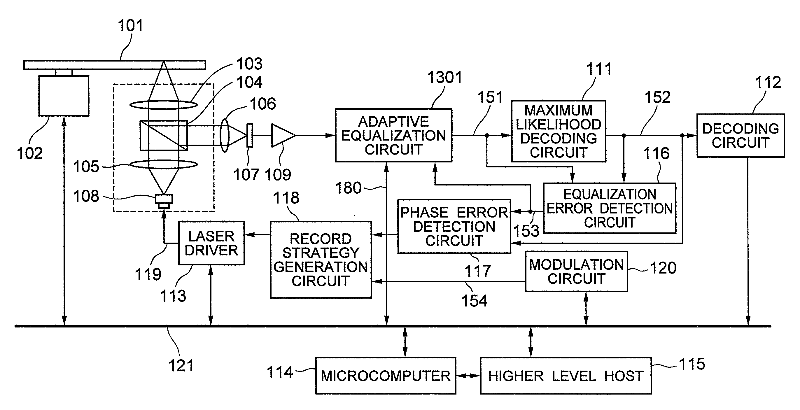
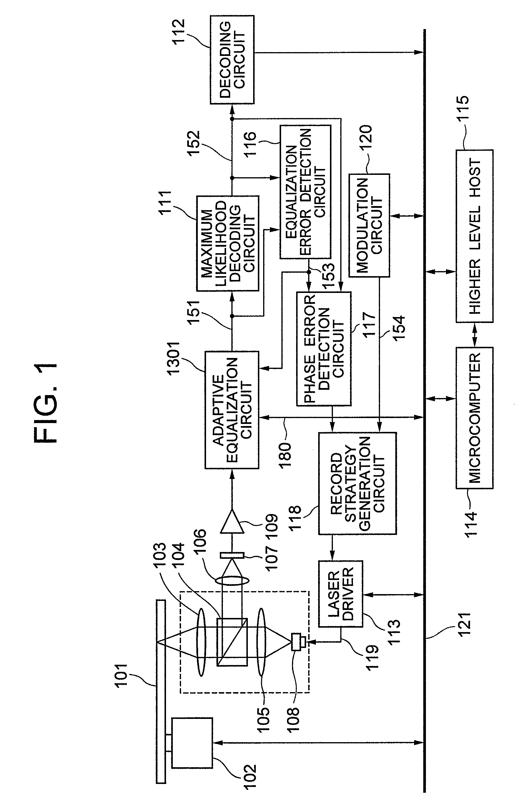
[0062]An optical disk apparatus according to an embodiment 3 of the present invention is shown in FIG. 11 as an example in which the foregoing is taken into consideration. In FIG. 11, blocks and elements with the same function as those shown in FIG. 1 are given the same reference numbers, and so the description thereof is omitted here.

[0063]1701 is a nonvolatile memory whose contents can be electrically rewritten, such as an EEPROM (Electrically Erasable and Programmable Read Only Memory). 1702 is a medium discrimination circuit....


PUM

PropertyMeasurementUnit
driving currentaaaaaaaaaa
transmissionaaaaaaaaaa
phase erroraaaaaaaaaa

Abstract

An optical disk apparatus is provided that has a signal processing circuit for equalizing a signal so as to achieve predetermined equalization, in which interference between codes is permitted, by means of an adaptive equalization circuit or the like, and for performing binarization by means of a maximum likelihood decoding circuit in which interference is performed as a rule, and thereby achieves stabilized signal reproduction in a narrow-band transmission. When evaluating the quality of the recorded signal through the use of the recording parameter learning and the reproduction system such as recorded signal verification, the optical disk recording apparatus is capable of highly precisely evaluating the quality of the recorded signal by fixing a circuit characteristic after suspending the optimization operation of the adaptive equalization circuit or the like for optimizing the characteristic by the reproduced signal. An optical disk recording method is also provided.

Description

CLAIM OF PRIORITY[0001]The present application claims priority from Japanese application JP-2006-308543 filed on Nov. 15, 2006 the content of which is hereby incorporated by reference into this application.BACKGROUND OF THE INVENTION[0002]The present invention relates to an optical disk apparatus for optically recording information on an optical disk through the use of laser light and to an optical disk recording method used in the optical disk recording apparatus.[0003]In the optical disk apparatus for recording data in the optical disk using laser light and reproducing binarized information from the optical disk, when recording the data, recording parameter learning is required for optimally adjusting the power and timing of a recording laser pulse (hereinafter referred to as “record strategy”)[0004]In the recording parameter learning, the quality of the record is evaluated based on the quality of reproduced recorded data. In this event, if data recording velocity differs from dat...

Claims


Application Information

Patent Timeline
Patent Type & Authority Applications(United States)
IPC IPC(8): G11B7/004G11B20/10G11B20/18
CPCG11B20/10055G11B20/10009G11B7/00458G11B20/18
Inventor NISHIMURA, KOICHIROIIZUKA, JUNYAKATSUKI, MANABUYASUKAWA, TAKAKIYO
Owner HITACHI CONSUMER ELECTRONICS CORP
Why Eureka
Try Eureka