Compound clearance control engine

a technology of compound clearance control and engine, which is applied in combination engines, machines/engines, mechanical equipment, etc., can solve the problems of reducing the overall reducing the efficiency of the engine, and losing the use of turbine cooling from the combustion cycle, so as to improve the efficiency and improve the effect of active clearance control

Active Publication Date: 2008-05-15
GENERAL ELECTRIC CO
View PDF8 Cites 117 Cited by
  • Summary
  • Abstract
  • Description
  • Claims
  • Application Information

AI Technical Summary

Problems solved by technology

Any air used for turbine cooling is lost from the combustion cycle and therefore reduces overall efficiency of the engine.
Leakage of the combustion gases at the blade tip gaps further decreases efficiency of the engine.
Accordingly, the radial blade tip clearance is made as small as practical but cannot be too small or undesirable rubbing of the blade tips against the turbine shroud can lead to undesirable damage or shortened component life.
Furthermore, as the engine is operated through various levels of power, the turbine components thermally expand and contract which correspondingly affects the size of the blade tip clearance.
In the various transient modes of operation of the engine where the power increases or decreases, the turbine shroud and blades expand and contract differently, which in turn affects the blade clearance.
In one particularly problematic mode of operation called reburst, engine power is quickly increased which correspondingly causes the turbine rotor blades to expand radially outwardly at a greater rate than that of the surrounding turbine shroud.
And, in order to avoid undesirable blade tip rubs against the turbine shroud the initial blade tip clearance must be set sufficiently large, which as indicated above will decrease overall efficiency of the engine due to blade tip leakage.
Nevertheless, the effectiveness of conventional active clearance control systems is limited and still requires a relatively large nominal blade tip clearance to avoid undesirable tip rubs, particularly during the reburst condition.
This blade cooling air bypasses the combustion process and therefore further reduces efficiency of the engine.

Method used


Image

  • Compound clearance control engine
  • Compound clearance control engine
  • Compound clearance control engine

Examples


Embodiment Construction

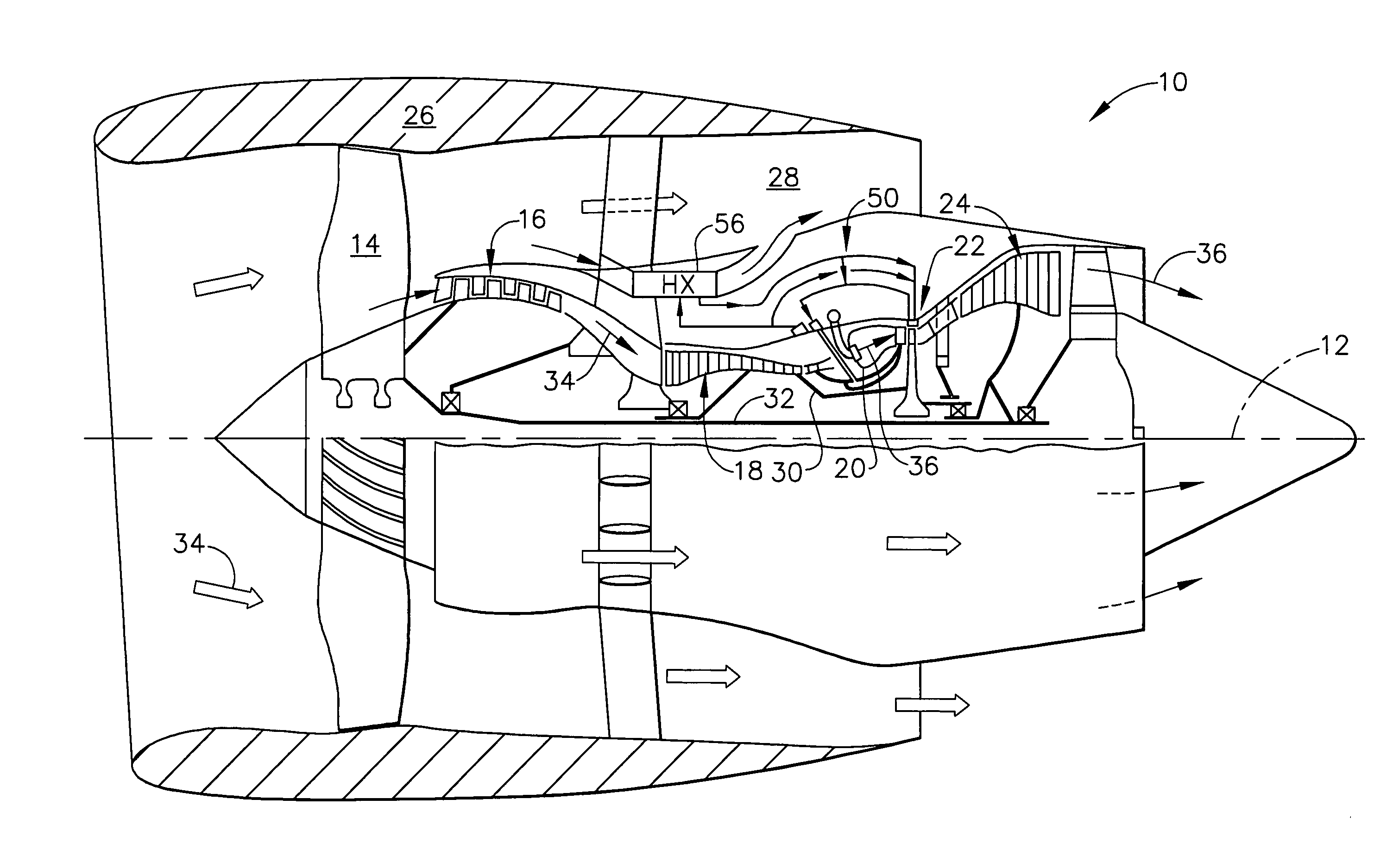
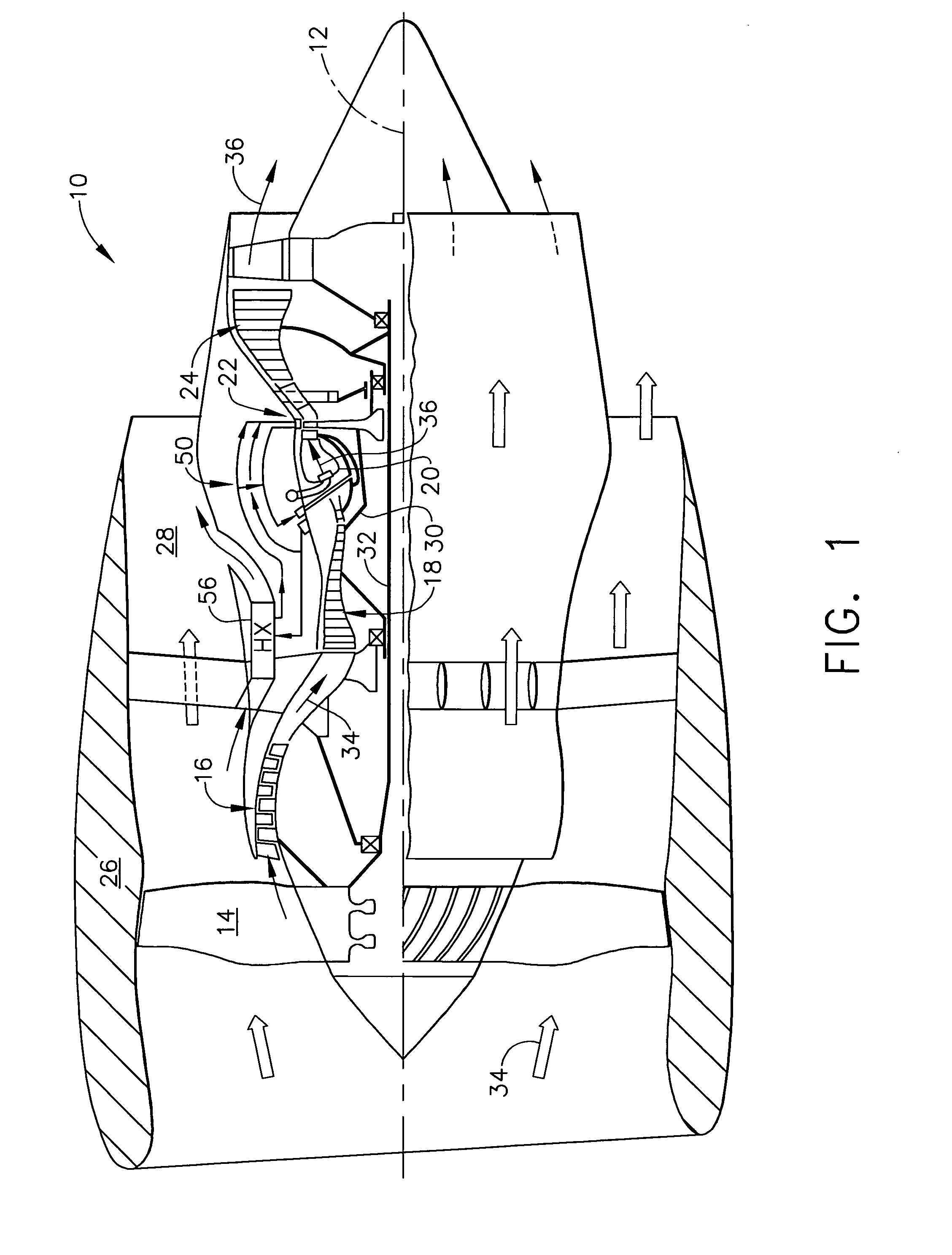
[0023]Illustrated schematically in FIG. 1 is an exemplary turbofan aircraft gas turbine engine 10. The engine is axisymmetrical about a longitudinal or axial centerline axis 12 and is suitably mounted to the wing or a fuselage of an aircraft (not shown) for powering an aircraft in flight in an exemplary application.

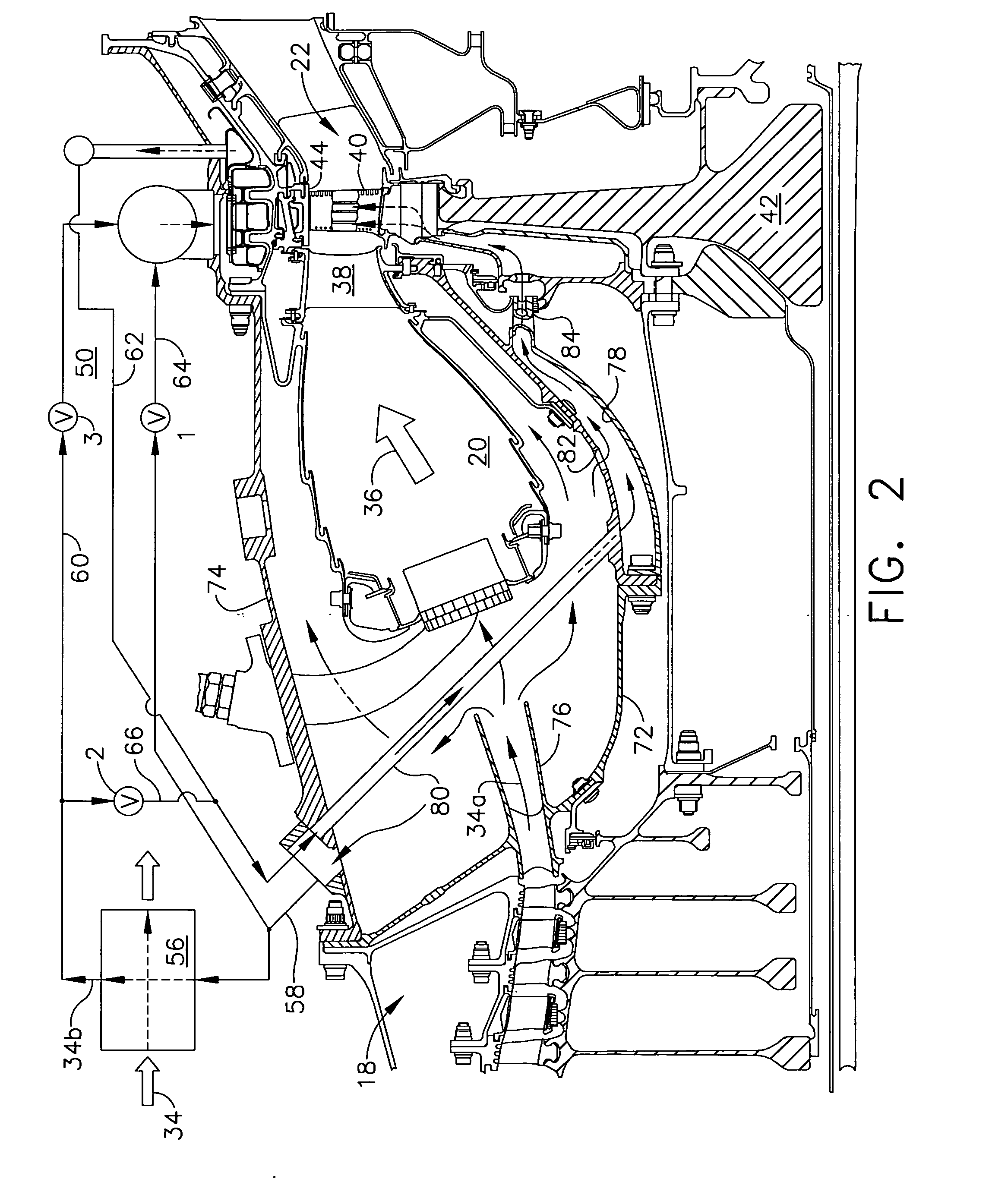
[0024]The engine includes in serial flow communication a fan 14, a low pressure or booster compressor 16, a high pressure (HP) compressor 18, an annular combustor 20, a high pressure turbine (HPT) 22, and a low pressure turbine (LPT) 24.

[0025]An annular nacelle 26 surrounds the fan 14 and defines an annular bypass duct 28 extending aft around the booster compressor 16. A first drive shaft 30 joins the HPT 22 to the HP compressor 18, and a second drive shaft 32 joins the LPT 24 to the fan 14 and booster compressor 16. The two drive shafts are suitably mounted in bearings in corresponding frames within- the engine in a conventional configuration of the various engine compon...


PUM


Abstract

A gas turbine engine includes a compressor, combustor, and turbine having a row of blades mounted inside a surrounding turbine shroud. A heat exchanger is used for cooling pressurized air bled from the compressor. A distribution network joins the heat exchanger to the turbine for selectively channeling air from the heat exchanger below the blades and above the shroud for controlling blade tip clearance.

Description

BACKGROUND OF THE INVENTION[0001]The present invention relates generally to gas turbine engines, and, more specifically, to active clearance control therein.[0002]In a gas turbine engine, air is pressurized in a compressor and mixed with fuel in a combustor for generating hot combustion gases. Energy is extracted from the gases in a high pressure turbine (HPT) which is joined by one drive shaft to the compressor.[0003]In a typical turbofan aircraft engine, a fan is mounted upstream from the compressor and is powered by a low pressure turbine (LPT) mounted downstream of the HPT. In marine and industrial (M & I) applications, the LPT powers an external drive shaft for powering a propulsion system or electrical generator in typical applications.[0004]The compression and combustion cycles introduce energy into the pressurized air, with energy extracted from the combustion gases in the turbine stages. Since the HPT is subject to the hottest combustion gases discharged from the combustor,...

Claims


Application Information

Patent Timeline
Patent Type & Authority Applications(United States)
IPC IPC(8): F02K3/04
CPCY02T50/672F01D11/24Y02T50/60
Inventor SEITZER, KENNETH EDWARDSAK, WOJCIECHDONG, ZHIFENGZIEGLER, ROBERT PAULGLYNN, CHRIS CHARLES
Owner GENERAL ELECTRIC CO
Why Eureka
Try Eureka