

Compressor
- Summary
- Abstract
- Description
- Claims
- Application Information
AI Technical Summary
Benefits of technology
Problems solved by technology
Method used
Image

Examples
first embodiment
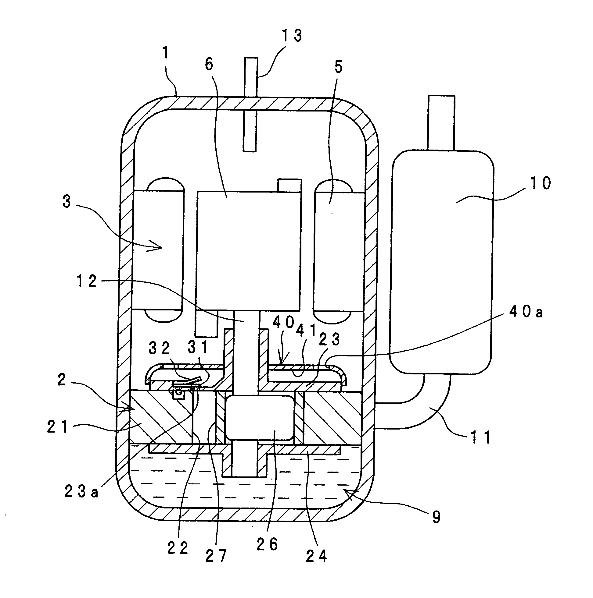
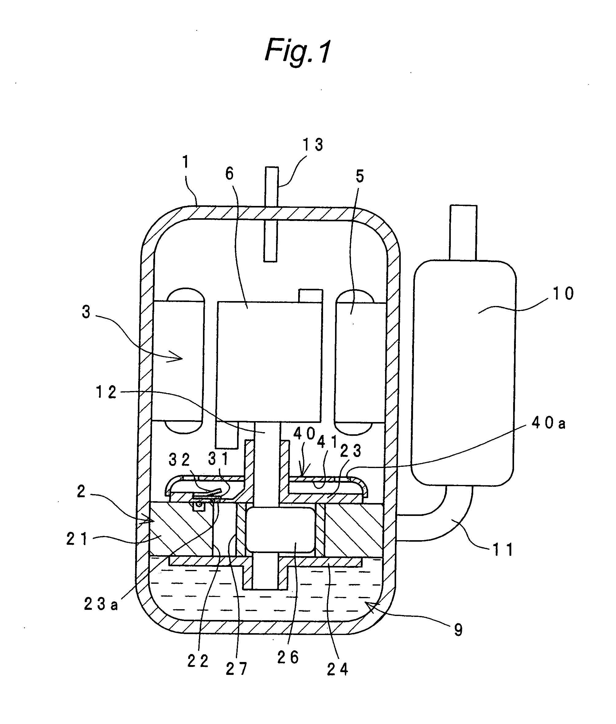
[0069]FIG. 1 shows a sectional view of a first embodiment of the compressor of the invention. The compressor of the invention is a rotary compressor of the so-called high-pressure dome type, in which a compression section 2 is placed below and a motor 3 is placed above within a casing 1. The compression section 2 is driven via a drive shaft 12 by a rotor 6 of the motor 3.
[0070]The compression section 2 sucks in a wet gas (refrigerant) through a suction pipe 11 from an accumulator 10. The wet gas can be obtained by controlling a condenser, an expansion mechanism and an evaporator (not shown) which constitute an air conditioner as an example of a refrigeration system together with this compressor.
[0071]The compressor discharges a compressed high-temperature, high-pressure discharge gas from the compression section 2 to fill the inside of the casing 1 therewith and, moreover, to cool the motor 3 through a clearance between a stator 5 and the rotor 6 of the motor 3, and thereafter disch...
second embodiment
[0093]FIG. 4 shows a second embodiment of the invention. In this second embodiment, a screw hole 42a of a valve holding member 42 is finished by burring process. The valve holding member 42 is made of a punched material of expandable steel. It is noted that component members designated by like reference numerals in conjunction with the first embodiment are identical in construction to those of the first embodiment, and so their description is omitted.
[0094]Thus, since the screw hole 42a of the valve holding member 42 is finished by burring process, an effective thread length can be ensured without increasing the thickness of the valve holding member 42. Also, a periphery of the screw hole 42a on one side on which the fixing bolt 33 is to be inserted through can be automatically chamfered so as to be rounded, providing a guide for insertion of the fixing bolt 33 to facilitate the assembly.
[0095]Since the valve holding member 42 is formed of a punched material of steel, the number of ...
third embodiment
[0096]FIG. 5 shows a third embodiment of the invention. In this third embodiment, an end-face member 53 has a discharge hole 53a through which compressed gas is discharged, and a through hole 53b into which the fixing bolt 33 is to be inserted through. A discharge valve 51 has a hole portion 51a through which the fixing bolt 33 is to be inserted, and a projecting portion 51b which projects into the discharge hole 53a of the end-face member 53. It is noted that component members designated by like reference numerals in conjunction with the first embodiment are identical in construction to those of the first embodiment, and so their description is omitted.
[0097]More specifically, the projecting portion 51b of the discharge valve 51 is formed into such a tapered configuration that the projecting portion 51b becomes thinner at its tip. The discharge hole 53a of the end-face member 53 is formed into a tapered configuration corresponding to the configuration of the projecting portion 51b....
PUM
 Abstract
Description
Claims
Application Information