Vascular Access Port with Catheter Connector

a vascular access port and catheter connector technology, which is applied in the direction of catheters, intravenous devices, other medical devices, etc., can solve the problems of difficult manual disconnecting of the catheter from the port in such an environment, the process of connecting the catheter to the reservoir of the vascular access port may be difficult for a practitioner, and the patient treatment could be compromised, etc., to achieve the effect of less insertion force and connection

Inactive Publication Date: 2008-05-15
ANGIODYNAMICS INC
View PDF60 Cites 136 Cited by
  • Summary
  • Abstract
  • Description
  • Claims
  • Application Information

AI Technical Summary

Benefits of technology

[0025]The present invention provides a catheter connector assembly for connecting a catheter to a vascular access port. The catheter connector assembly of the present invention is advantageous in view of current vascular acce...

Problems solved by technology

Otherwise, patient treatment could be compromised.
The process of connecting the catheter to the reservoir of the vascular access port may be difficult for a practitioner because the practitioner's gloves, as well as the vascular access port, may be wet and slippery inside of the patient's body as a result of contact with bodily fluids or other solutions.
Furthermore, if the catheter and the port need to be separated so that the catheter or port can be removed or exchanged, it can be difficult to manually disconnect the catheter from the port in such an environment.
The longer it takes the practitioner to connect or disconnect the catheter to the vascular access port, the greater the chance that effective treatment of the patient might be compromised.
Otherwise, the function of the catheter and the vascular access port can be impaired, causing an increase in inflammatory and thrombotic complications or extravasal administration of drugs.
Dislocation or disconnection of the catheter from the port may also require the port to be removed in some cases, which can increase procedure time and cause unwanted complications.
Such alignment can be difficult to accomplish in a wet or slippery environment while wearing gloves.
It can also be difficult to connect the catheter to the vascular access port stem because both the stem and the catheter lumen may be very small.
When a catheter lumen is advanced over a...

Method used


Image

  • Vascular Access Port with Catheter Connector
  • Vascular Access Port with Catheter Connector
  • Vascular Access Port with Catheter Connector

Examples


Embodiment Construction

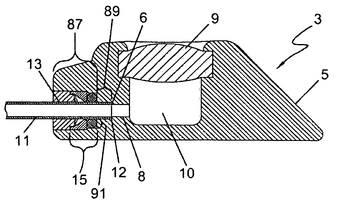
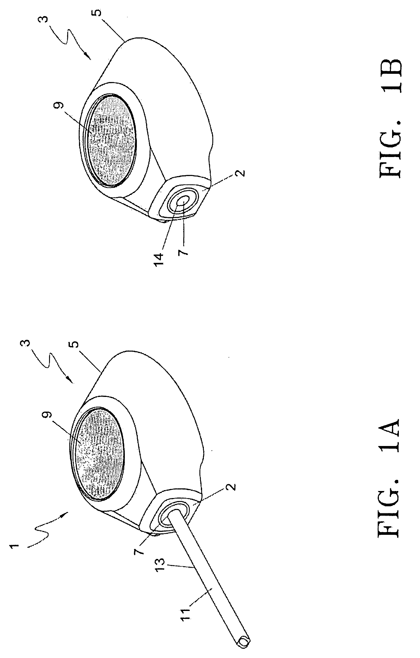
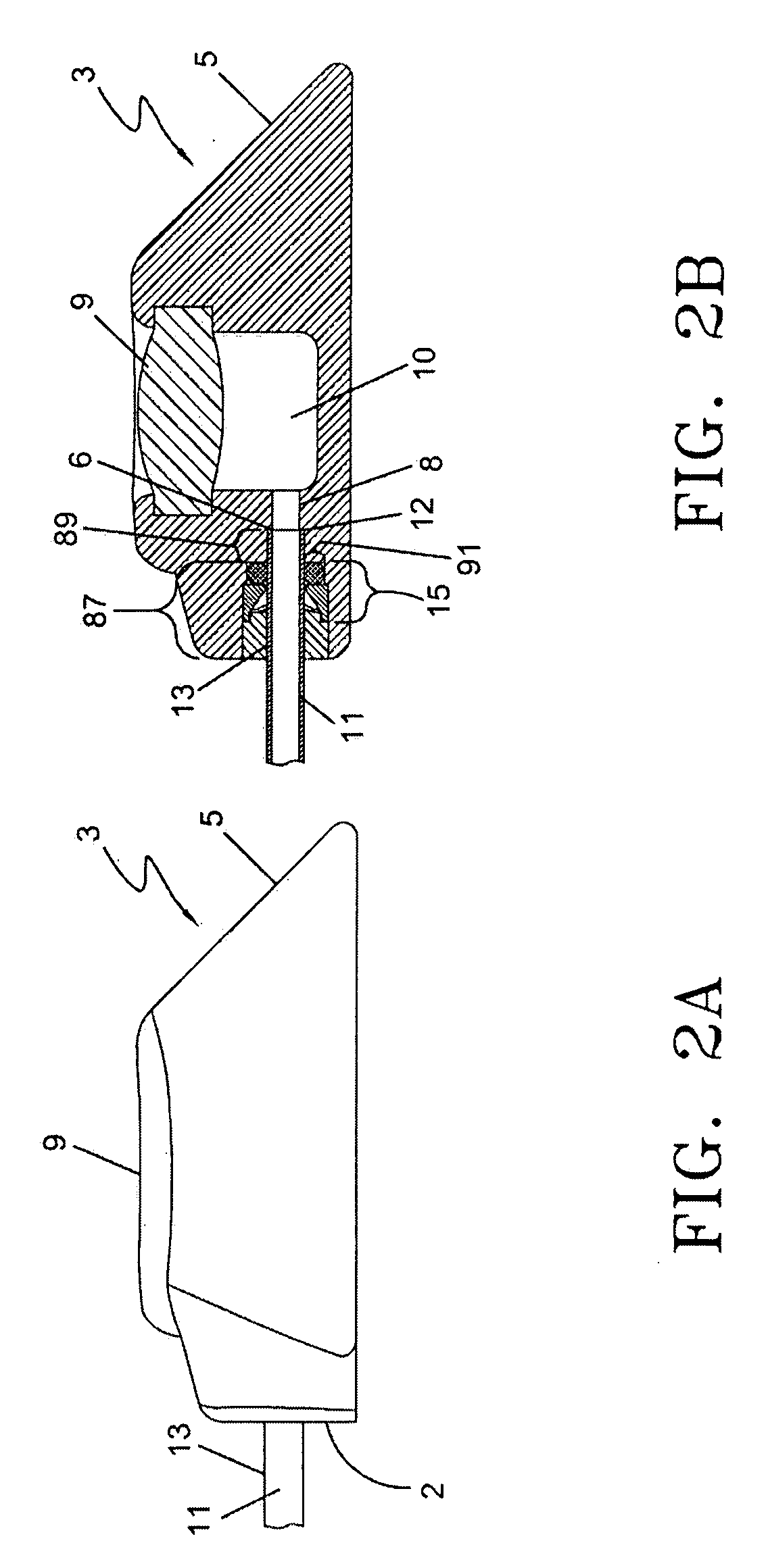
[0047]The following detailed description should be read with reference to the drawings, in which like elements in different drawings are identically numbered. The drawings, which are not necessarily to scale, depict selected preferred embodiments and are not intended to limit the scope of the invention. The detailed description illustrates by way of example, not by way of limitation, the principles of the invention. The present invention is illustrated in FIGS. 1 through 11.

[0048]The present invention is more particularly described in the following exemplary embodiments that are intended to be illustrative only since numerous modifications and variations therein will be apparent to those skilled in the art. As used herein, “a,”“an,” or “the” can mean one or more, depending upon the context in which it is used. The preferred embodiments are now described with reference to the figures, in which like reference characters indicate like parts throughout the several views.

[0049]Ranges may...


PUM


Abstract

An implantable vascular access port assembly that has a septum, a reservoir, and a catheter connector assembly for use in connecting a catheter with the vascular access port. The catheter connector assembly has an O-ring, an O-ring seal, a locking ring, and a catheter connection plug, which components are located in secured adjacent relationship to one another, respectively, in the vascular access port. The catheter connector assembly securely locks the catheter inside of the vascular access port without compromising the lumen cross-sectional area and can withstand high pressures.

Description

CROSS-REFERENCE TO RELATED APPLICATIONS[0001]This application claims priority to and the benefit of U.S. Provisional Application No. 60 / 865,533, filed on Nov. 13, 2006, which application is incorporated in its entirety in this document by reference.FIELD OF THE INVENTION[0002]The present invention relates to the field of implanted vascular access devices. Particularly, the present invention pertains to the field of vascular access ports. More particularly, the present invention pertains to catheter connection devices for use with vascular access ports.BACKGROUND OF THE INVENTION[0003]Implanted vascular access devices provide venous access to the central circulatory system of a patient. Vascular access ports are vascular access devices that are implanted into a patient's vascular system for applications in which repeated access to a patient's vascular system is necessary. Repeated access could be for the purpose of infusion of medications, prolonged intravenous feeding of fluids such...

Claims


Application Information

Patent Timeline
IPC IPC(8): A61M5/00A61M31/00A61M39/10A61M37/00A61M39/00A61M25/16A61M25/18
CPCA61M39/0208A61M39/10A61M2205/32A61M39/12A61M2039/1072A61M39/1011
Inventor DI PALMA, GIORGIOMITCHELL, JAMES J.HAMILTON, WILLIAM C.
Owner ANGIODYNAMICS INC
Why Eureka
Try Eureka