
Engine Response Adjustment Based on Traffic Conditions

a technology of engine response and traffic conditions, applied in the direction of electric control, brake systems, instruments, etc., can solve problems such as feeling sluggish, and achieve the effects of improving fuel economy, reducing emissions, and increasing fuel economy

Active Publication Date: 2008-05-15
FORD GLOBAL TECH LLC
View PDF26 Cites 63 Cited by
  • Summary
  • Abstract
  • Description
  • Claims
  • Application Information

AI Technical Summary

Benefits of technology

[0002]For example, a higher gain relationship may be desired for some lower pedal depression and / or lower vehicle speed conditions to provide a more “peppy” vehicle feel. This can be especially true when a vehicle is designed with a more under-powered powertrain in order to increase fuel economy and / or reduce emissions. In other words, a smaller engine and / or otherwise adjusted transmission may provide improved fuel economy, but may feel sluggish during acceleration driver tip-ins from lower speeds.
[0003]On the other hand, a lower gain relationship may be desired for other lower pedal depression and / or lower vehicle speed conditions to provide finer engine and / or vehicle output torque control to give the operator improved ability in torque selection and adjustment. This can be especially true during driving maneuvers under increased traffic conditions and / or during maneuvers such as vehicle parking or traversing rough terrain.
[0005]Likewise, a driver may select also provide some selectivity based on a desired fuel economy performance, such as through a driver selectable fuel economy switch, as to how the gain is adjusted in response to such information, thereby providing gain adjustment that is more sensitive to driver needs and / or goals. In one embodiment, by integrating gain adjustment using both environmental information and driver selectable fuel economy information, it may be possible to provide improved drivability over a variety of conditions while providing the operator with desired fuel economy performance in a smooth and coordinated way.

Problems solved by technology

However, there may be conflicting goals in tuning the pedal relationship to vehicle output response based on numerous factors.
In other words, a smaller engine and / or otherwise adjusted transmission may provide improved fuel economy, but may feel sluggish during acceleration driver tip-ins from lower speeds.

Method used


Image

  • Engine Response Adjustment Based on Traffic Conditions
  • Engine Response Adjustment Based on Traffic Conditions
  • Engine Response Adjustment Based on Traffic Conditions

Examples


Embodiment Construction

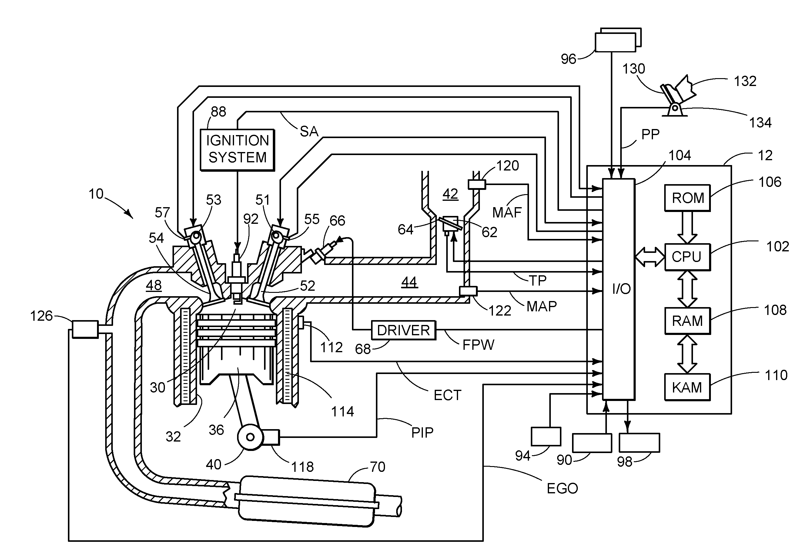
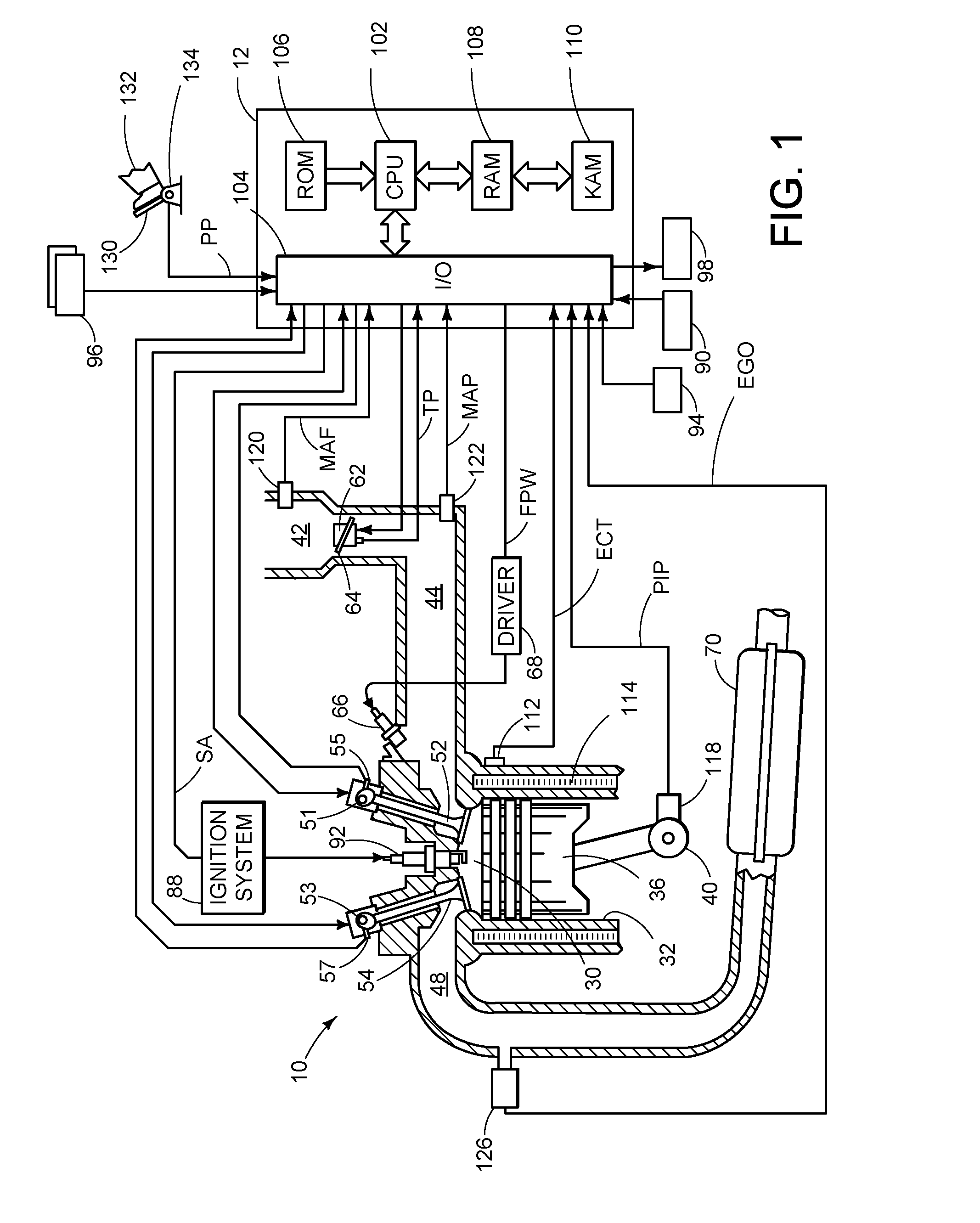
[0010]FIG. 1 shows a schematic diagram of one cylinder of multi-cylinder internal combustion engine 10. Combustion chamber or cylinder 30 of engine 10 is shown including combustion chamber walls 32 and piston 36 positioned therein and connected to crankshaft 40. A starter motor (not shown) may be coupled to crankshaft 40 via a flywheel (not shown). Cylinder 30 may communicate with intake port 44 and exhaust port 48 via respective intake valve 52 and exhaust valve 54. Intake valve 52 and exhaust valve 54 may be actuated via intake camshaft 51 and exhaust camshaft 53. Further, the position of intake camshaft 51 and exhaust camshaft 53 may be monitored by intake camshaft sensor 55 and exhaust camshaft sensor 57 respectively. Intake and / or exhaust valve control may also be provided by signals supplied by controller 12 via electric valve actuation (EVA). Additionally intake and exhaust valves may be controlled by various other mechanical control systems including cam profile switching (C...


PUM


Abstract

A method for controlling an engine of a vehicle in response to an operator input, comprising of during a first non-cruise control condition and at first distance to a forward vehicle, adjusting engine output in response to said operator input with a first relationship; and during a second non-cruise control condition and at second, greater, distance to a forward vehicle, adjusting engine output in response to said operator input with a second relationship different from said first.

Description

BACKGROUND AND SUMMARY[0001]Vehicles systems receive various operator commands in order to facilitate operator control of the powertrain, including an accelerator foot pedal input. Further, the relationship between the amount of operator depression and the powertrain response can be tuned to provide different drive feel and performance, and can be adjusted based on various engine or vehicle operating conditions. However, there may be conflicting goals in tuning the pedal relationship to vehicle output response based on numerous factors.[0002]For example, a higher gain relationship may be desired for some lower pedal depression and / or lower vehicle speed conditions to provide a more “peppy” vehicle feel. This can be especially true when a vehicle is designed with a more under-powered powertrain in order to increase fuel economy and / or reduce emissions. In other words, a smaller engine and / or otherwise adjusted transmission may provide improved fuel economy, but may feel sluggish duri...

Claims


Application Information

Patent Timeline
Patent Type & Authority Applications(United States)
IPC IPC(8): B60T7/12B60W30/16
CPCB60W30/16B60W2540/10F02D11/105F02D2250/18F02D41/2422F02D2200/501F02D2200/606F02D41/021
Inventor DOERING, JEFF
Owner FORD GLOBAL TECH LLC
Learn More