Pulse detonation engine bypass and cooling flow with downstream mixing volume

a technology of bypassing and cooling flow, which is applied in the direction of machines/engines, hot gas positive displacement engine plants, intermittent jet plants, etc., can solve the problems of damage to these components, adversely affecting the overall operation of the engine, and loss, so as to achieve optimal downstream operation and enhance the mixing of pdc exhaus

Inactive Publication Date: 2008-05-22
GENERAL ELECTRIC CO
View PDF9 Cites 21 Cited by
  • Summary
  • Abstract
  • Description
  • Claims
  • Application Information

AI Technical Summary

Benefits of technology

[0010]A further embodiment of the present invention includes a mixing chamber, including a plenum, located at the exit of the PDC and bypass flow nozzle. This chamber enhances mixing of the PDC exhaust and bypass air. This enhanced mixing assists the PDC exhaust and bypass air i

Problems solved by technology

One problem, which often arises when employing PDCs in a “hybrid” engine configuration, is the presence of losses due to unsteady pressure waves that are generated by the pulse detonation process.
This often causes flow reversals within these conventional components which can da

Method used


Image

  • Pulse detonation engine bypass and cooling flow with downstream mixing volume
  • Pulse detonation engine bypass and cooling flow with downstream mixing volume
  • Pulse detonation engine bypass and cooling flow with downstream mixing volume

Examples


Embodiment Construction

[0020]The present invention will be explained in further detail by making reference to the accompanying drawings, which do not limit the scope of the invention in any way.

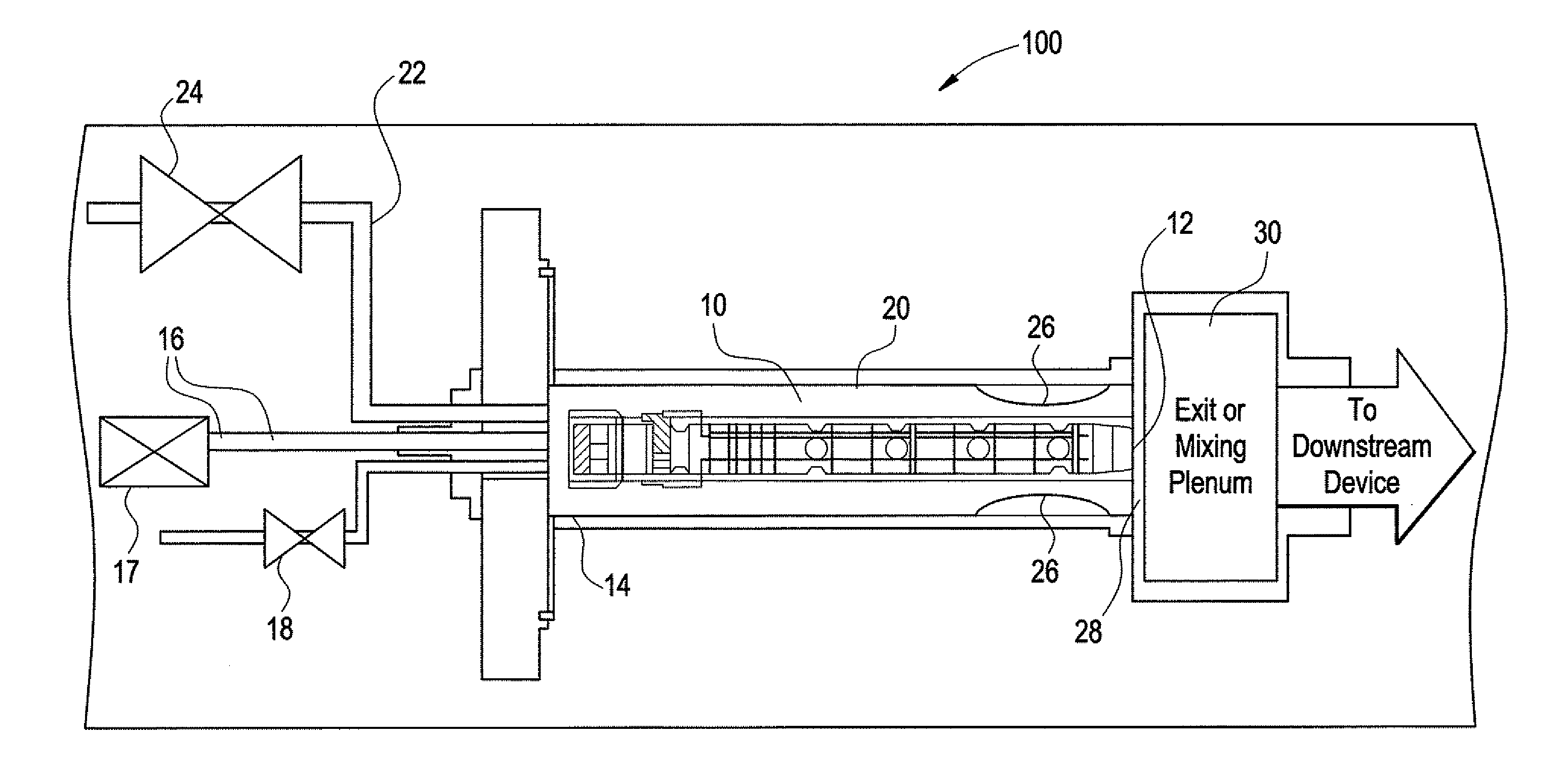
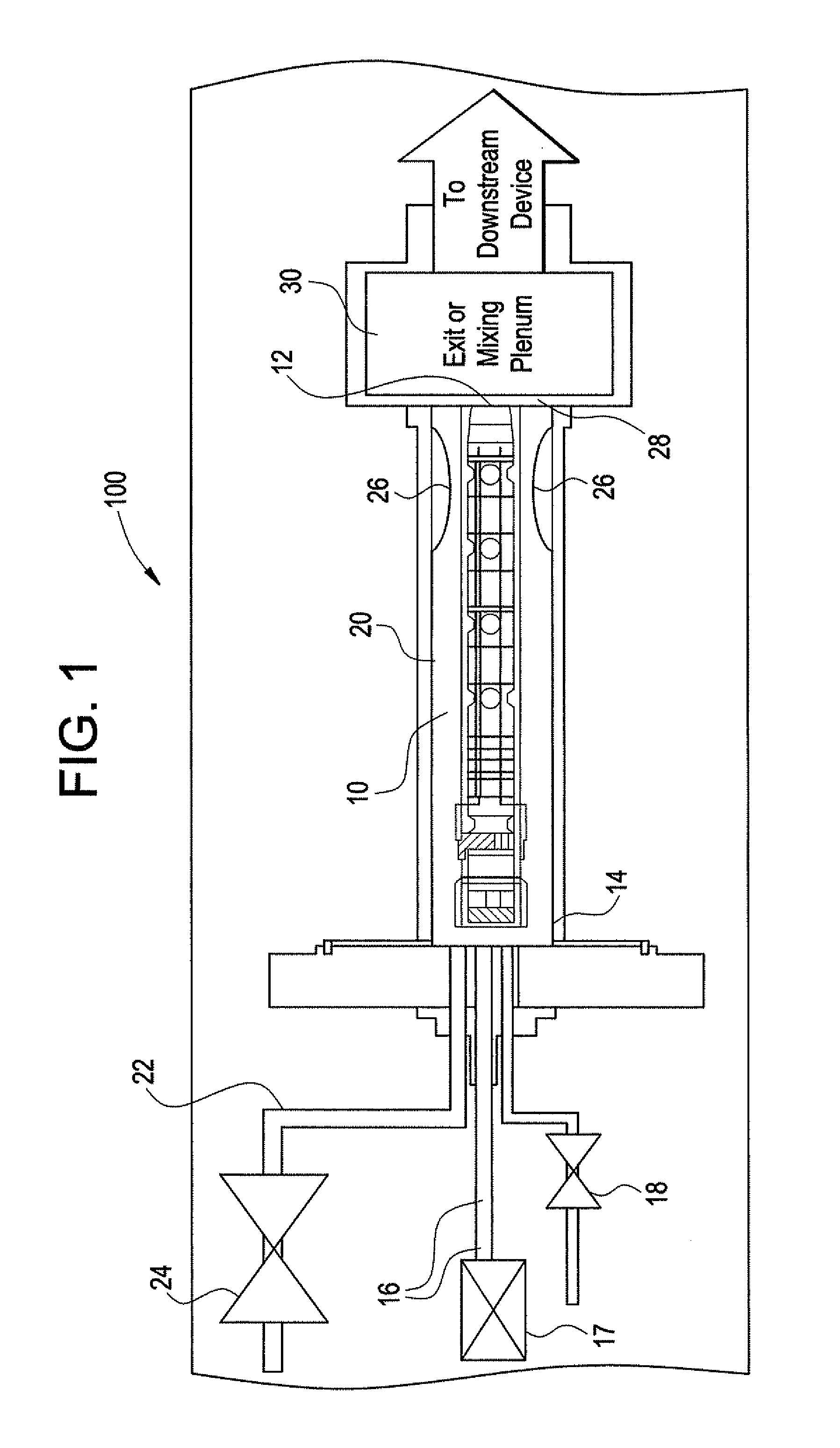
[0021]FIG. 1 depicts an engine 100 having at least one pulse detonation combustor 10 having an exit nozzle 12 and an input portion 14. Air flow for the combustor 10 is provided from a primary air flow source 16, which can be from a compressor stage (not shown) of the engine 100, or comparable source. The primary air flow may also be controlled by a primary air control valve 17. Fuel is supplied to the combustor 10 via a high frequency fuel control valve 18.

[0022]The fuel control valve 18 may be controlled by any known or conventional means. In the present invention, it is contemplated that the valve 18 be controlled so as to modulate or regulate heat release from the working fuel. Namely, the fuel, and detonation, control is such that the generation of heat by the combustor 10 can be set to the appropriate level fo...


PUM


Abstract

An engine contains at least one pulse detonation combustor which is surrounded by a bypass flow air duct, through which bypass air flow is directed. The bypass air duct contains at least one converging-diverging structure to dampen or choke the upstream propagation of shock waves from the pulse detonation combustor through the bypass flow air duct. The bypass air also serves to cool the outer surfaces of the pulse detonation combustor. The bypass air flow is controlled in tandem with the heat release from the PDC to provide the appropriate amount of thermal energy to a downstream energy conversion device, such as a turbine. A mixing plenum is positioned downstream of the pulse detonation combustor and bypass flow air duct.

Description

BACKGROUND OF THE INVENTION[0001]This invention relates to pulse detonation systems, and more particularly, to a pulse detonation engine bypass and cooling flow, with downstream mixing volume.[0002]With the recent development of pulse detonation combustors (PDCs) and engines (PDEs), various efforts have been underway to use PDC / Es in practical applications, such as combustors for aircraft engines and / or as means to generate additional thrust / propulsion in a post-turbine stage. Further, there are efforts to employ PDC / E devices into “hybrid” type engines which use a combination of both conventional gas turbine engine technology and PDC / E technology in an effort to maximize operational efficiency. It is for either of these applications that the following discussion will be directed. It is noted that the following discussion will be directed to “pulse detonation combustors” (i.e. PDCs), However, the use of this term is intended to include pulse detonation engines, and the like.[0003]On...

Claims


Application Information

Patent Timeline
IPC IPC(8): F02C5/00
CPCF02C5/02F02K7/04F02C5/11
Inventor RASHEED, ADAMDEAN, ANTHONY JOHNPINARD, PIERRE FRANCOISVANDERVORT, CHRISTIAN LEETANGIRALA, VENKAT ESWARLU
Owner GENERAL ELECTRIC CO
Why Eureka
Try Eureka