High temperature enclosure system for flare gas sampling

a high temperature enclosure and gas sampling technology, applied in the field of oil refineries, can solve the problems of not allowing vapors, gas or liquids to “backtrack” and maintaining positive air pressure inside the enclosure,

Inactive Publication Date: 2008-05-22
MANGAN
View PDF2 Cites 7 Cited by
  • Summary
  • Abstract
  • Description
  • Claims
  • Application Information

AI Technical Summary

Benefits of technology

[0021]In the present invention, only one sample line is required to feed one sample pump. After the sample line has been discharged by the pump, it can run to as many analyzers as desired, hence one probe, one delivery line, one pump, and a multiplicity of devices can be fed from one sample. This insures the readings of the analyzers are from the same sample regardless of what components are being analyzed. This is done while maintaining high temperatures in a Class 1, Division 2, Groups B, C & D area.

Problems solved by technology

If a leak occurs inside the heated enclosure, the positive air pressure maintained inside the enclosure does not allow the vapor, gas or liquid to build to an explosive concentration.
However this is prevented because air is forced pass the heater element into the enclosure, creating positive pressure, thus not allowing any vapors to “backtrack” to the heater.
If this should occur, the inventive enclosure turns itself off, gradually cooling off while the heater has been turned off, not allowing it to continue operating while the plant air is off.

Method used


Image

  • High temperature enclosure system for flare gas sampling
  • High temperature enclosure system for flare gas sampling
  • High temperature enclosure system for flare gas sampling

Examples


Embodiment Construction

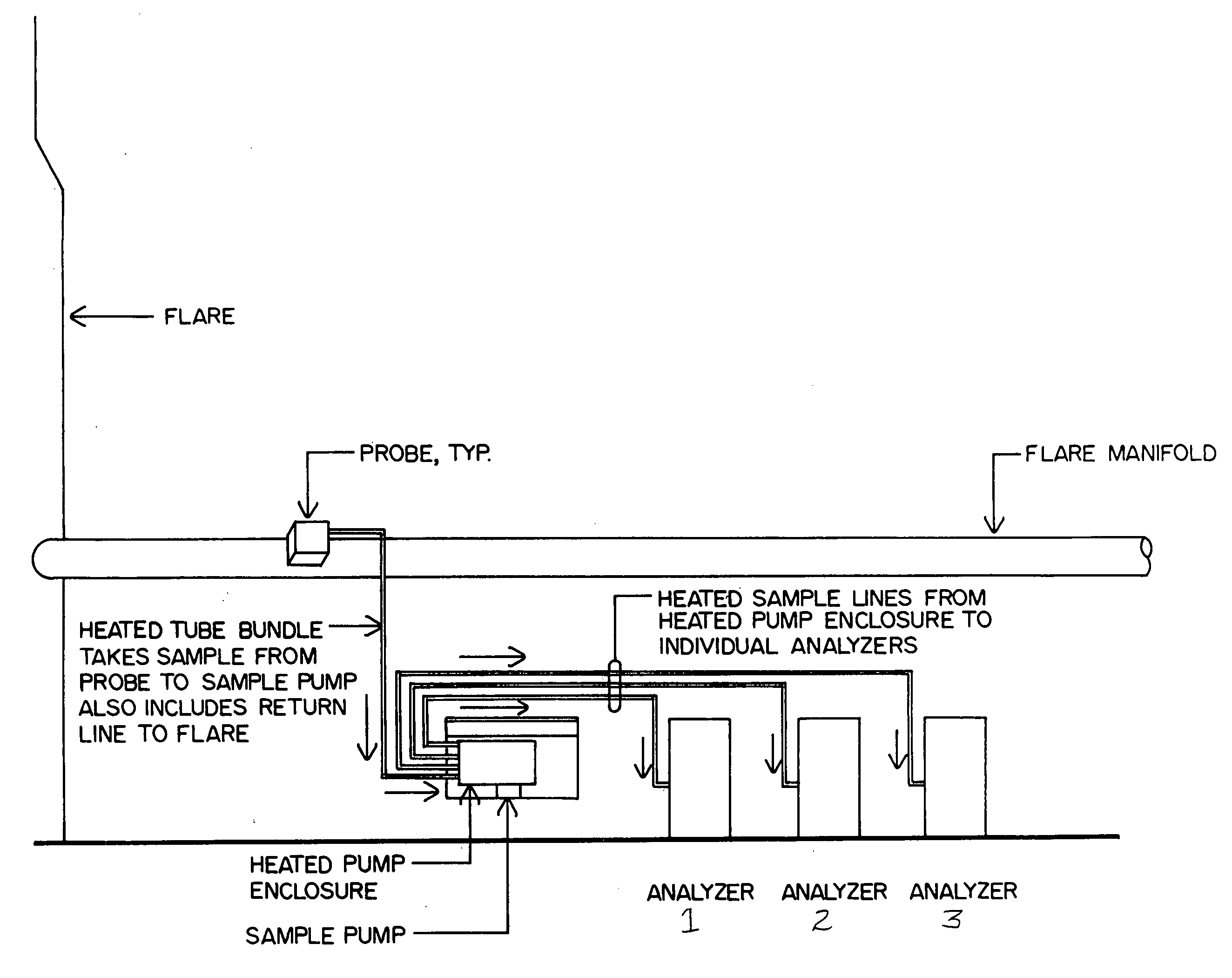
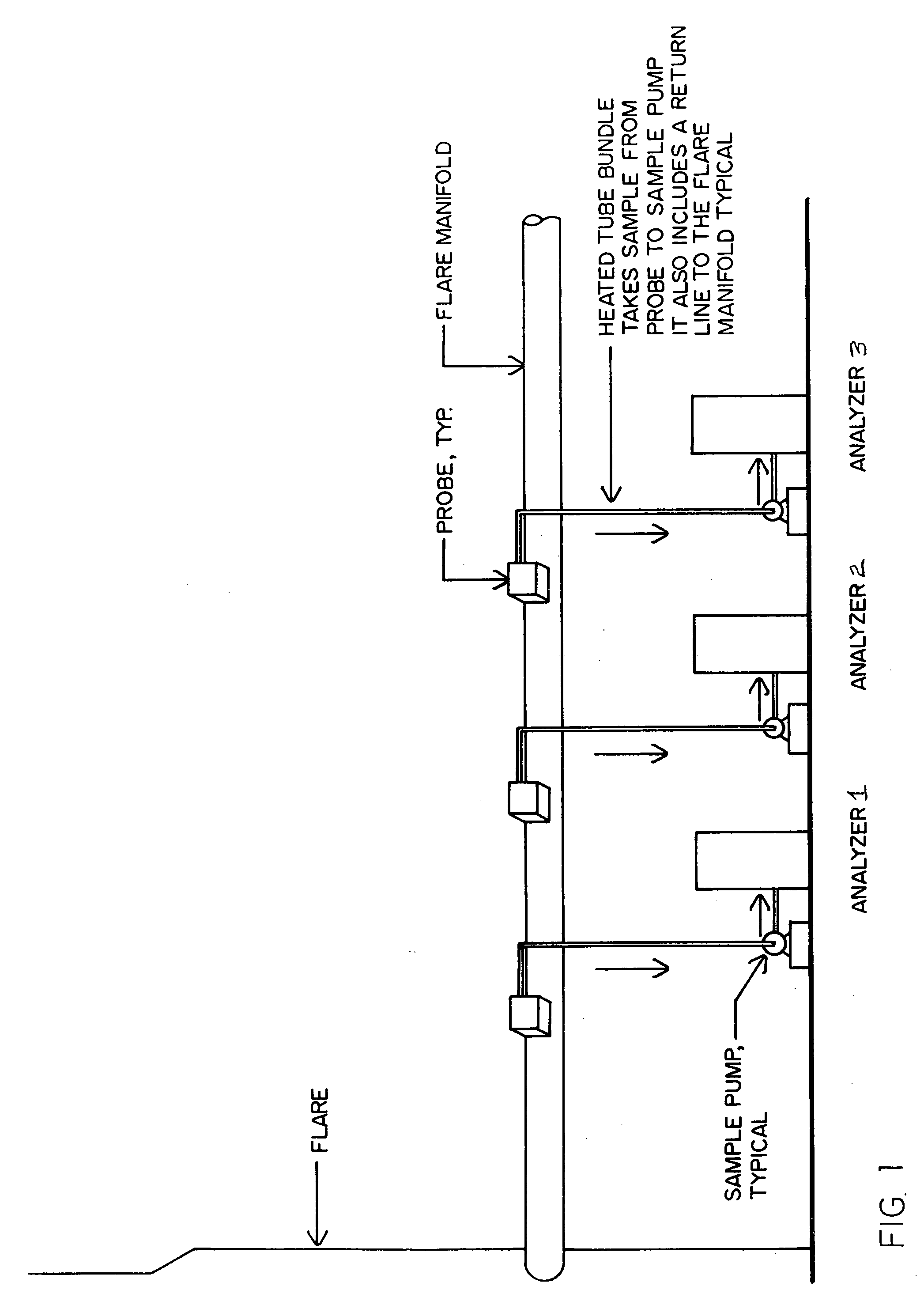
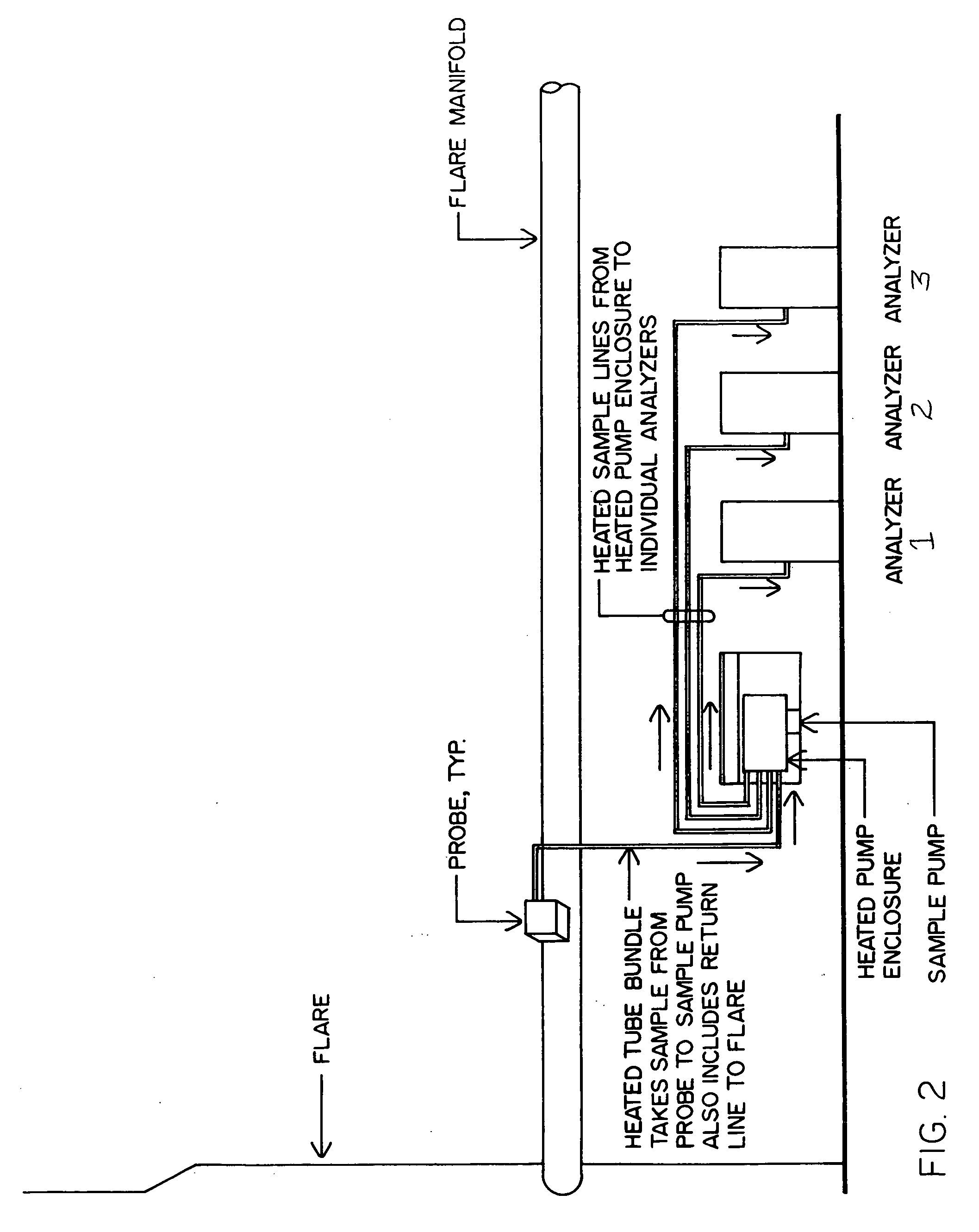
[0027]FIG. 1 illustrates the prior art method of gathering samples from the flare manifold and distributing the sample to the various analyzers involved. As can be seen each analyzer requires its own system of delivery, pump and probe. FIG. 2 illustrates the Heated Pump Assembly as the sole recipient of the heated tube line from the only probe mounted on the flare manifold. From the Heated Probe Assembly multiple heated tube lines are distributed to the analyzers, as many analyzers as required. FIG. 3, consisting of FIGS. 3A, 3B and 3C, is an interior view of the Heated Pump Assembly.

[0028]The various features of the Heated Pump Assembly are identified in FIG. 3. Starting with FIG. 3C, the heated tube bundle from the probe is shown entering the heated enclosure. It is routed to the suction side of the pump head, which is located at the bottom of the enclosure (FIG. 3B). After the sample side is discharged from the pump head, it is routed through a series of tubing tee's and valves t...


PUM

PropertyMeasurementUnit
temperaturesaaaaaaaaaa

Abstract

A heated sample pump enclosure maintains a regulated high temperature for the head of a pump as well as a plurality of sample lines that pass through it. The pump receives a flare sample from a process line and then discharges it to any number of external devices while maintaining a constant temperature, as it is being switched and routed within the heated enclosure. There are electrical, thermo and process safety shutdown systems that regulate and monitor the process within the enclosure by means of electrical instrumentation and temperature controls. The enclosure as well as the required equipment is preferably packaged as a unit.

Description

CROSS-REFERENCE TO RELATED APPLICATIONS[0001]This application takes priority from U.S. Provisional Application Ser. No. 60 / 859,767 filed Nov. 16, 2006.BACKGROUND OF THE INVENTION[0002]1. Field of the Invention[0003]The present invention relates generally to the field of oil refineries and specifically to the field of flare gas sampling wherein a sampling gas pump head is provided in an enclosure along with a plurality of sample lines while the enclosure interior is maintained at a constant high temperature to improve the accuracy of sampling analysis.[0004]2. Background Art[0005]Flares are primarily intended as safety and pollution control devices. They burn gases that cannot be used by the refinery and prevent their direct release to the atmosphere.[0006]A number of different devices may be called flares. A flare, as defined, is a combustion device that uses an open flame to burn combustible gases with combustion air provided by uncontrolled ambient air surrounding the flame. The t...

Claims


Application Information

Patent Timeline
Patent Type & Authority Applications(United States)
IPC IPC(8): G01N1/22
CPCG01N1/2258G01N1/18
Inventor KOHLHAGEN, GUYER LEEKIM, MU HONGSOLEHJOU, AMIN
Owner MANGAN
Why Eureka
Try Eureka