Liquid film applicator assembly and rectilinear shearing system incorporating the same

Active Publication Date: 2008-05-22
FIBRALIGN CORP
View PDF18 Cites 13 Cited by
  • Summary
  • Abstract
  • Description
  • Claims
  • Application Information

AI Technical Summary

Benefits of technology

[0013]The present invention refers to devices intended for controlled coating substrate surfaces with liquid (flowable) substances and forming the desired material structure due to the shear between two planes sliding relative to each other. The aim of this inventi

Problems solved by technology

In the clamping mechanism, the tightening screws directly presses against the blade which imparts a twisting motion to the blade However, neither this accuracy of this device nor (which is more important) the mode of device interaction with the applied liquid are sufficient for the formation of high-quality optically anisotropic films and coatings, especially such as are employed in modern multilayer interference devices.
However, devices known in the prior art do not ensure the formation of highly anisotropic films with reproducible characteristics, which is explained by unavoidable disruption of the oriented molecular structure (defect production) during the film formation.
In addition, the technology of film form

Method used


Image

  • Liquid film applicator assembly and rectilinear shearing system incorporating the same
  • Liquid film applicator assembly and rectilinear shearing system incorporating the same
  • Liquid film applicator assembly and rectilinear shearing system incorporating the same

Examples


Embodiment Construction

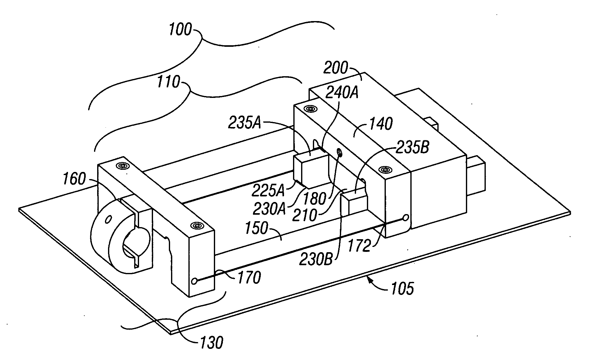
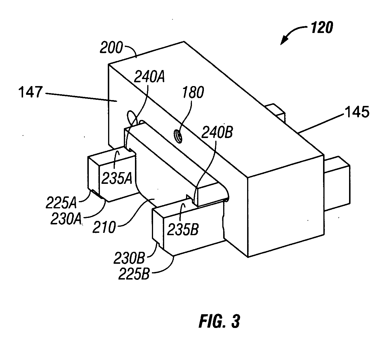
[0042]Referring now primarily to FIG. 1 a Coating Device 100 according to the disclosed invention comprises an Applicator Assembly 120 (FIG. 3), and a Compliant Assembly 110.

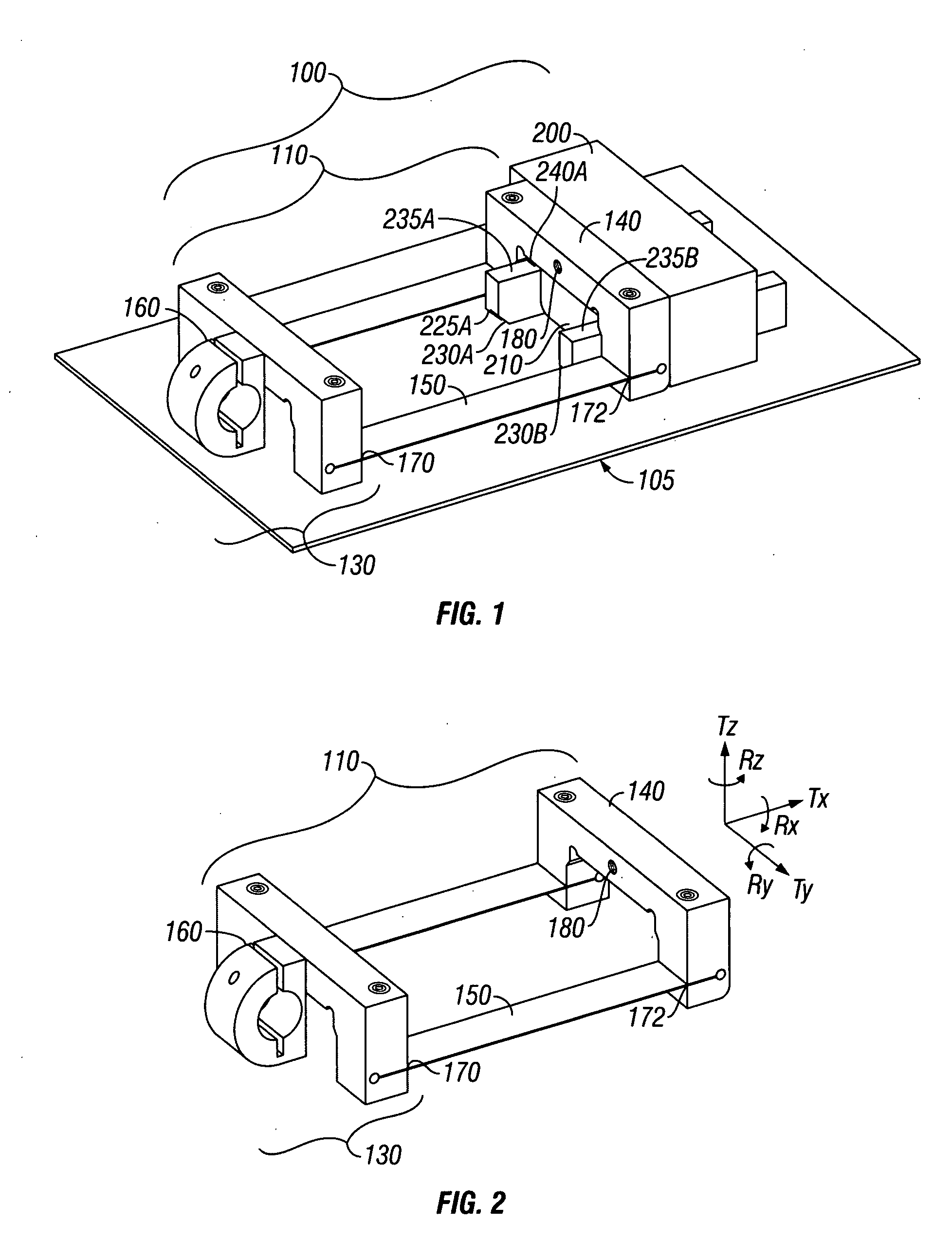
[0043]The Applicator Assembly 120 is securely attached to one end of the Compliant Assembly 110 and the other end of Compliant Assembly is secured to fixed a mechanical anchor (not shown) via Clamp 160 (FIG. 2). Further details of both the Complaint Assembly and the Applicator Assembly will be discussed below.

[0044]The Coating Solution that is to be formed into a thin film is placed on the Substrate 105 just in front of Bridge 210. Then Substrate 105 is moved from left to right, causing Coating Solution 108 to be dragged under Applicator Assembly 120 causing Thin Film Coating 109 to be formed.

[0045]All references to motion and direction of motion of the substrate are to be understood to be relative to the coating device. It is possible to have the coating assembly fixed to an anchor and the substrate move. Alter...


PUM

PropertyMeasurementUnit
Angleaaaaaaaaaa
Angleaaaaaaaaaa
Angleaaaaaaaaaa

Abstract

A liquid coating applicator with a very precise means for controlling gap thickness as well as adapting to non-planar discontinuities in the substrate.

Description

RELATED APPLICATIONS[0001]This application claims benefit of the provisional application 60 / 860,230 filed on 21 Nov. 2006.FIELD OF THE INVENTION[0002]The present invention refers to the field of formation of thin-film coatings using flowable substances. More specifically, the invention refers to facilities for obtaining thin films or coatings possessing anisotropic physical properties.BACKGROUND OF THE INVENTION[0003]Various types of wet film applicators, in particular, those used for testing paints, are known from the prior art. For the correct determination of some special properties of coatings such as color, transparency, luster, strength, resistance to weathering and chemical factors, etc., it is necessary to ensure that the test coatings applied in sequential runs would have the same preset thickness. In addition, it is desired that the applicator device would be adjustable so as to obtain the films of the desired thickness from various substances having varied physical proper...

Claims


Application Information

Patent Timeline
IPC IPC(8): B05B7/00
CPCB05C11/028G02B5/3083G02B5/3016
Inventor MCMURTRY, DAVID HARWOODPAUKSHTO, MIKHAIL VITOLDOVICHBOBROV, YURI A.
Owner FIBRALIGN CORP
Why Eureka
Try Eureka