Protective cover

Inactive Publication Date: 2008-05-22
CHEMTRON RES
View PDF5 Cites 2 Cited by
  • Summary
  • Abstract
  • Description
  • Claims
  • Application Information

AI Technical Summary

Benefits of technology

[0014]The advantage of the present invention lies in that, the two heat sinks coated with the thermal conducting mediums are respectively fixed on the plate body, so that the thermal conducting mediums may be completely encapsulated in the accommodation space of the two opposite plate surfaces, thereby ensuring the integrity and the property of the thermal conductivity of the thermal conducting mediums. Meanwhile, as two heat sinks can be mounted on a single protective cover simultaneously, thus greatly saving the packaging materials

Problems solved by technology

However, during the transportation of the heat sinks, the thermal conducting medium is easily contaminated by the ambient environment or distorted by scratching or extrusion, resulting in the increase of the coating area of the thermal conducting medium and even the peeling off of the thermal conducting medium.
Thus, when the manufacturers fabricate and deliver a large quantity of the heat sinks, more protective covers are required, which is inevitably a heavy burden

Method used


Image

  • Protective cover
  • Protective cover
  • Protective cover

Examples


first embodiment

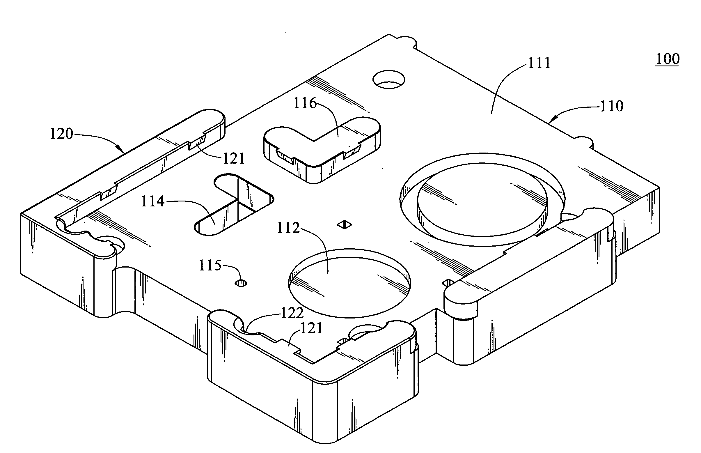
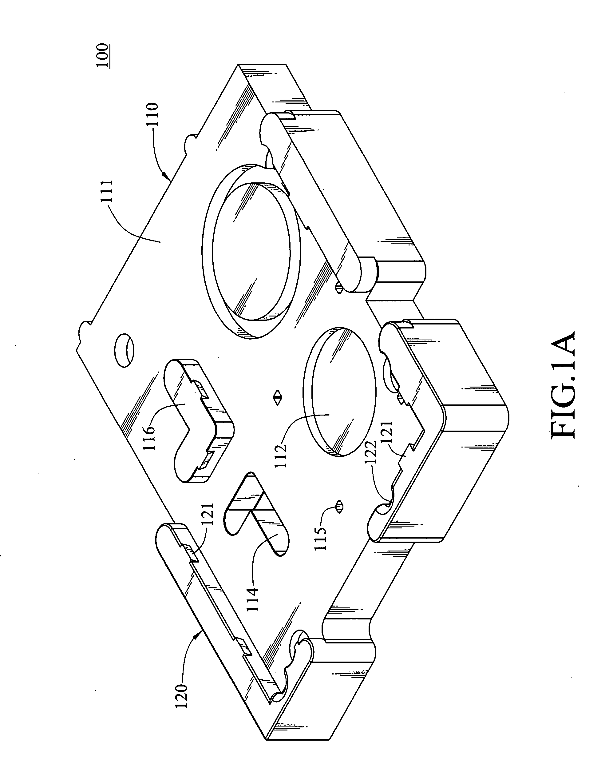
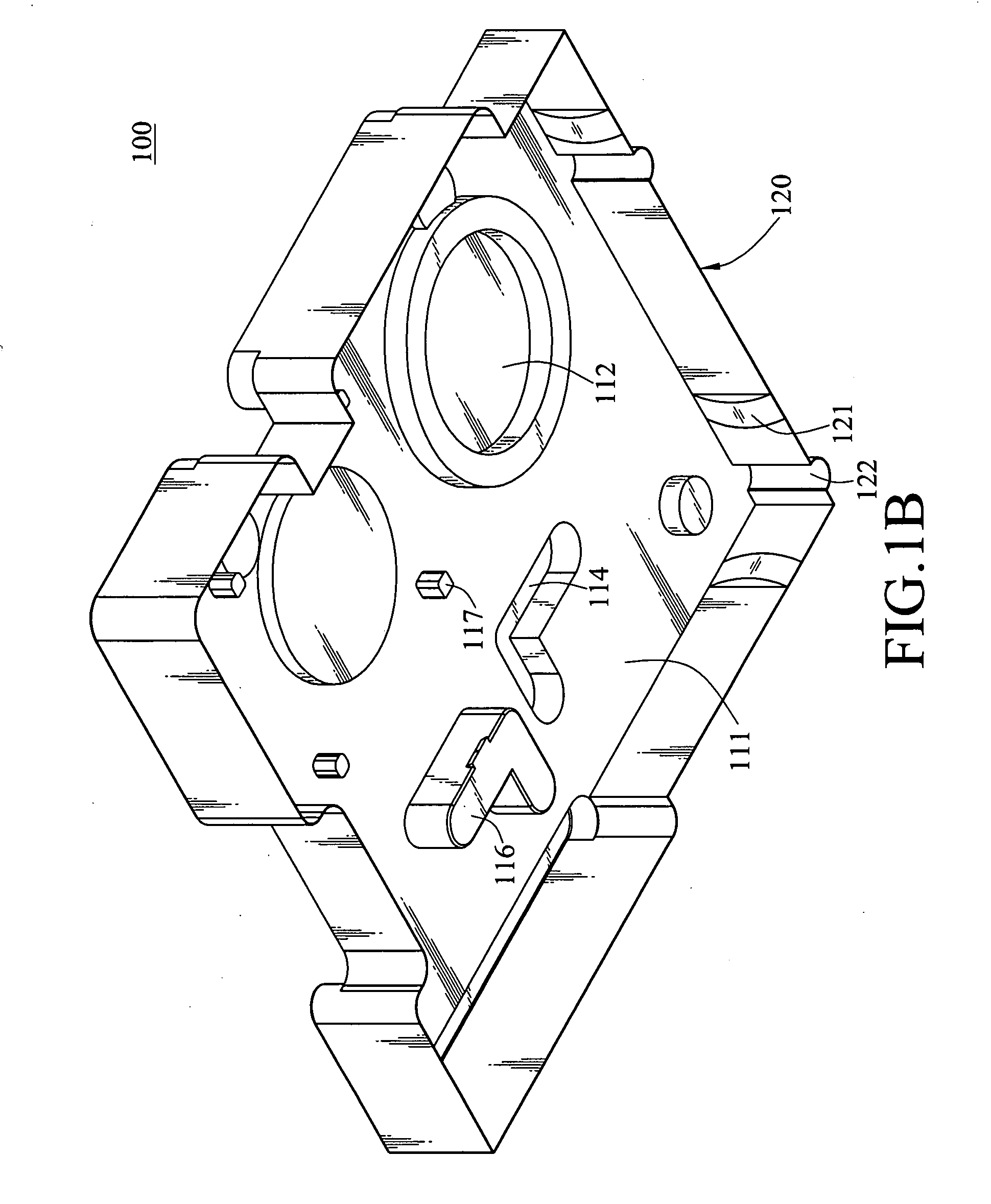
[0036]FIGS. 1A to 1F are schematic views of the present invention. As shown in the figures, the protective cover 100 provided by the present invention may simultaneously protect the thermal conducting mediums 210 coated on the bottoms of two heat sinks 200, so as to protect the thermal conducting mediums 210 from being contaminated or peeling off. The protective cover 100 of the present invention includes a plate body 110 and two holding portions 120. The plate body 110 has two opposite plate surfaces 111 respectively covering the bottoms of the two heat sinks 200 coated with the thermal conducting medium 210. One side of the plate body 110 is designed to be a frame structure with an accommodation space, so a side wall extends vertically to the periphery of one plate surface 111, thereby forming a holding portion 120. A side wall is protruded from the edge of the other side of the plate body 110, so as to form another holding portion 120 at the side of the other plate surface 111. T...

second embodiment

[0039]FIGS. 2A to 2F are schematic views of the present invention. The plate body 110 of the present invention has two opposite plate surfaces having a plurality of columnar support members 113 protruding therefrom. When the plate body 110 covers the bottoms of the two heat sinks 200, the top ends of the support members 113 rest on the bottoms of the heat sinks 200, so that the thermal conducting medium 210 may be accommodated in the space between the support members 113 and the plate surface 111, and is separated from the plate surface 111 by a distance without contacting the plate surface 111.

[0040]Referring to FIGS. 2A to 2F, a plurality of recess holes 115 corresponding to the support members 113 on one plate surface 111 is formed on the plate surface 111 on the other side. Moreover, an L-shaped recess portion 114 corresponding to the size of the heat sinks 200 is formed on the plate surfaces 111 respectively, so that the protruding portions of the heat sinks 200 may be engaged ...

third embodiment

[0041]FIGS. 3A to 3G are schematic views of the present invention. A protection cavity 112 corresponding to the thermal conducting medium 210 is recessed on one of the two opposite plate surfaces 111 of the plate body 110, and a plurality of columnar support members 113 are formed on the other plate surface 111. When the plate body 110 covers the bottom of the heat sink 200, the thermal conducting medium 210 may be just accommodated in the protection cavity 112. Or, the bottom of the heat sink 200 rest on the top ends of the support members 113, so that the thermal conducting medium 210 is separated from the plate surface 111 by a distance without contacting the plate surface 111.

[0042]As shown in FIGS. 3A to 3G, a plurality of recess holes 115 corresponding to the support members 113 formed on one plate surface 111 is formed on the plate surface 111 at the other side. Furthermore, an L-shaped recess portion 114 corresponding to the size of the heat sink 200 is respectively formed o...


PUM


Abstract

A protective cover is used for protecting thermal conducting mediums on two heat sinks from being damaged simultaneously. The protective cover includes a plate body and two holding portions. The plate body has two opposite plate surfaces respectively covering the sides of the two heat sinks coated with a thermal conducting medium. The two holding portions are formed on the periphery of the two plate surfaces and surround the two plate surfaces to form an accommodation space respectively. The holding portions are engaged with the two heat sinks and cover the thermal conducting mediums in the accommodation space respectively.

Description

CROSS-REFERENCE TO RELATED APPLICATIONS[0001]This non-provisional application claims priority under 35 U.S.C. §119(a) on Patent Application No(s). 095220595 filed in Taiwan, R.O.C. on Nov. 22, 2006, the entire contents of which are hereby incorporated by reference.BACKGROUND OF THE INVENTION[0002]1. Field of Invention[0003]The present invention relates to a protective cover, and more particularly to a protective cover capable of simultaneously accommodating two heat sinks and the thermal conducting mediums thereon.[0004]2. Related Art[0005]With the rapid development of computer science and technology, the operating speed of electronic components is gradually increased, and the integrated circuits (IC) become highly integrated, so that a large amount of heat is generated during the operation of the electronic components. If the heat is not dissipated in time, the operation performance of computer devices will be seriously influenced.[0006]In order to reduce the working temperature of...

Claims


Application Information

Patent Timeline
IPC IPC(8): B65D85/30
CPCH01L21/4871H01L21/50H01L23/367H01L23/3737H01L2924/0002H01L2924/00
Inventor HU, RUI XIA
Owner CHEMTRON RES
Why Eureka
Try Eureka