Vehicle Having An Adjustable Wheel Base

a technology of adjustable wheels and wheels, which is applied in the direction of folding cycles, cycles, transportation and packaging, etc., can solve the problem of no proposal related to a specific structure, and achieve the effect of preventing interference by the main frame, simple structure, and easy adjustment of the amount of movemen

Inactive Publication Date: 2008-05-22
TOYOTA SHATAI KK +1
View PDF5 Cites 38 Cited by
  • Summary
  • Abstract
  • Description
  • Claims
  • Application Information

AI Technical Summary

Benefits of technology

[0009]By using a structure in which the drive of the operating apparatus urges and rotates the rotating arms, centered about the portions that are connected to the main frame, the rear wheels are moved in a longitudinal direction with respect to the front wheels. At the same time, the inclination of the main frame is changed and the inclination of the vehicle seat is changed in cooperation with the change in the wheel base. It is possible thereby to adjust the size of the wheel base and the inclination of the vehicle seat to a state that is appropriate for the traveling conditions by using a simple structure. In addition, by selecting a position urged by the operating portion in a vertical direction from among the parts of the rotating arms, it is possible to easily adjust the amount of movement of the rear wheels and the amount of the inclination of the vehicle seat with respect to the amount of operation of the operating apparatus. In addition, it is possible to realize a vehicle having an adjustable wheel base that is small and provides for freedom of design.Invention According to Aspect 2
[0010]Because the operating apparatus is connected to the rotating arms via the operating links, the operating portion of the operating apparatus does not pivot significantly due to the operation thereof, and it is possible to prevent interference by the main frame. Additionally, the amount of movement of the operating portion can be reduced, and it is possible to increase the freedom of design in the layout of each of the mechanisms.Invention According to Aspect 3
[0011]It is possible to sufficiently operate the operating apparatus because the operating links are disposed on the outside of the main frame in the transverse direction so as to avoid the main frame in the transverse direction when the pair of sub-links are connected together, and these operating links are connected to the vehicle in the transverse direction at the portion where these sub-links are connected together by the operating portion of the operating apparatus. And at the same time, it is possible to significantly increase the freedom of design because the rotating arms are rotated without the main frame interfering with the operating links.Invention According to Aspect 4
[0012]It is possible to realize an operating apparatus that is quiet and has little vibration because the operating portion of the operating apparatus is configured by a male screw member that is threaded on the outer circumferential surface thereof and that is rotated by an electric motor, and a female screw member that has the male screw member threaded therein, which is rotatably connected to the operating link, and that moves linearly thereon due to the rotation of the male screw member.Invention According to Aspect 5
[0013]Since the lower ends of the upper arms and the upper ends of the lower arms are rotatably connected, and subsequently the upper ends of the upper arms are connected to locations of the main frame positioned farther toward the rear than the locations of the main frame that are connected to the rotating arms, the lower ends of the lower arms are connected to the rear wheels, and one of the upper arms or the lower arms are rotatably connected to the main frame and the rear wheels, it is possible to prevent vibration from occurring in the main frame while the vehicle is traveling because the upper arms and the lower arms support the main frame along with the rotating arms. In addition, it is possible to decrease the load burden on the rotating arms.

Problems solved by technology

Up until the present, however, there has been no proposal related to a specific structure for linking the change in the wheel base with the inclination of the vehicle seat.

Method used


Image

  • Vehicle Having An Adjustable Wheel Base
  • Vehicle Having An Adjustable Wheel Base
  • Vehicle Having An Adjustable Wheel Base

Examples


Embodiment Construction

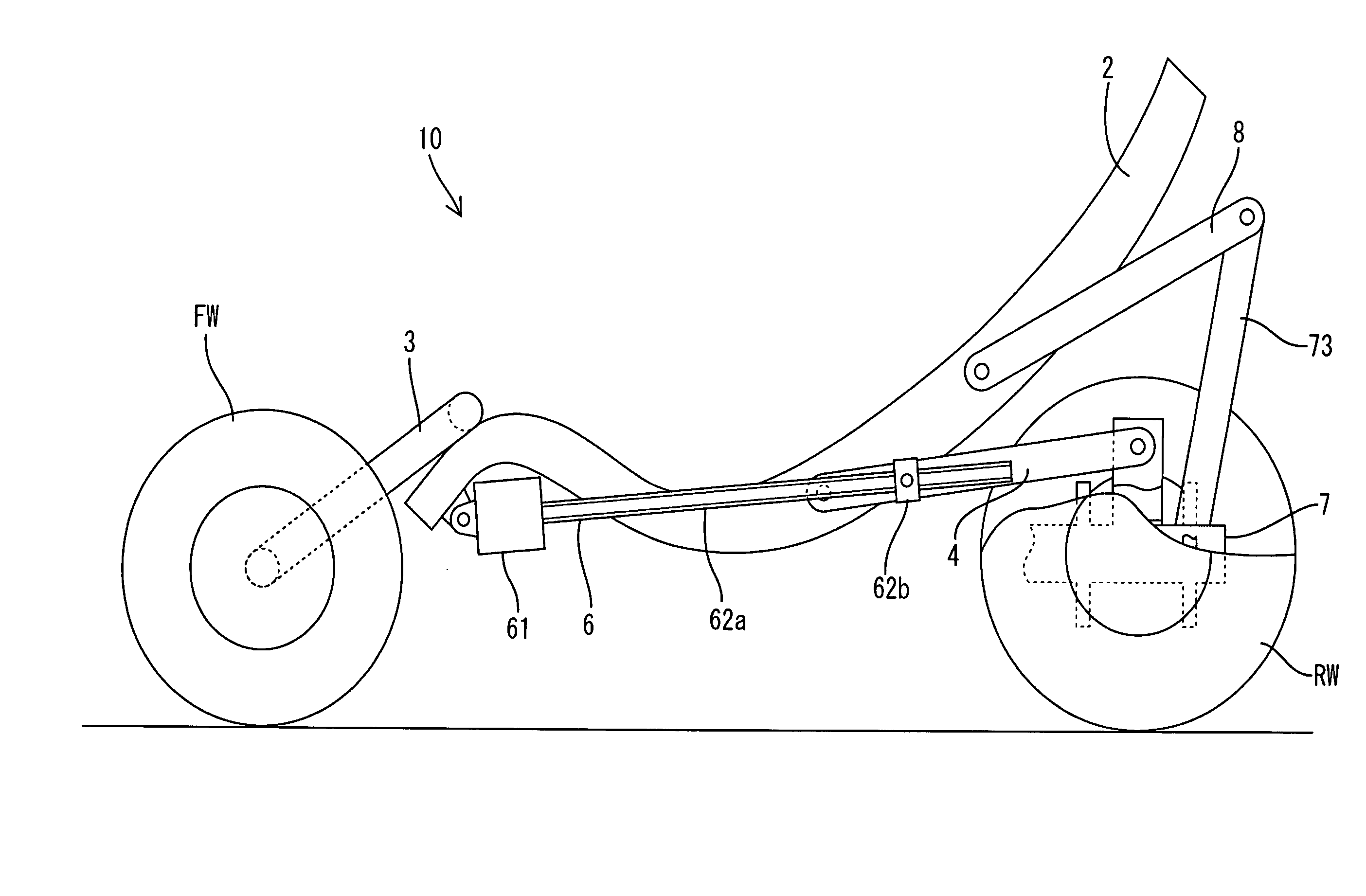
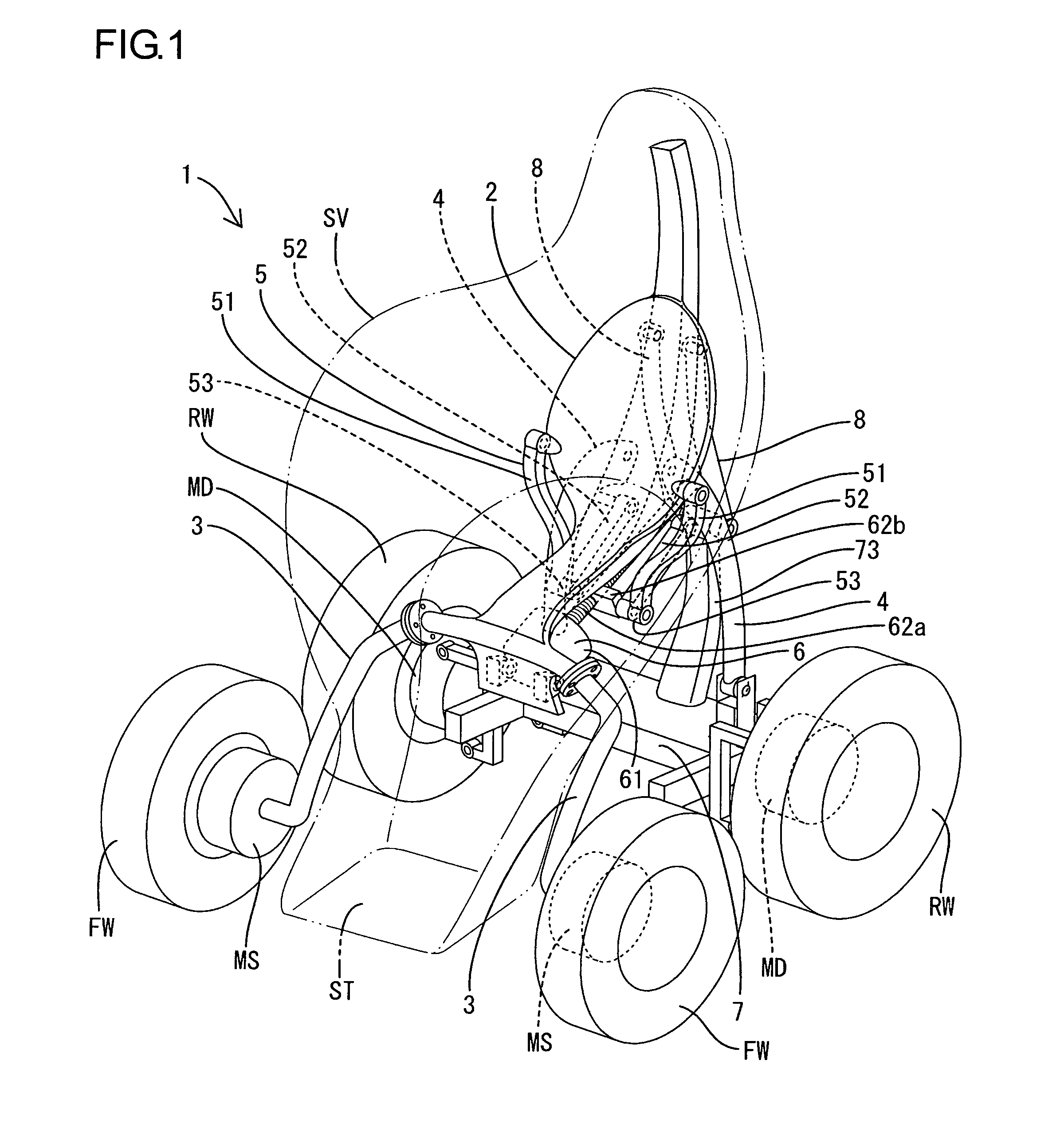
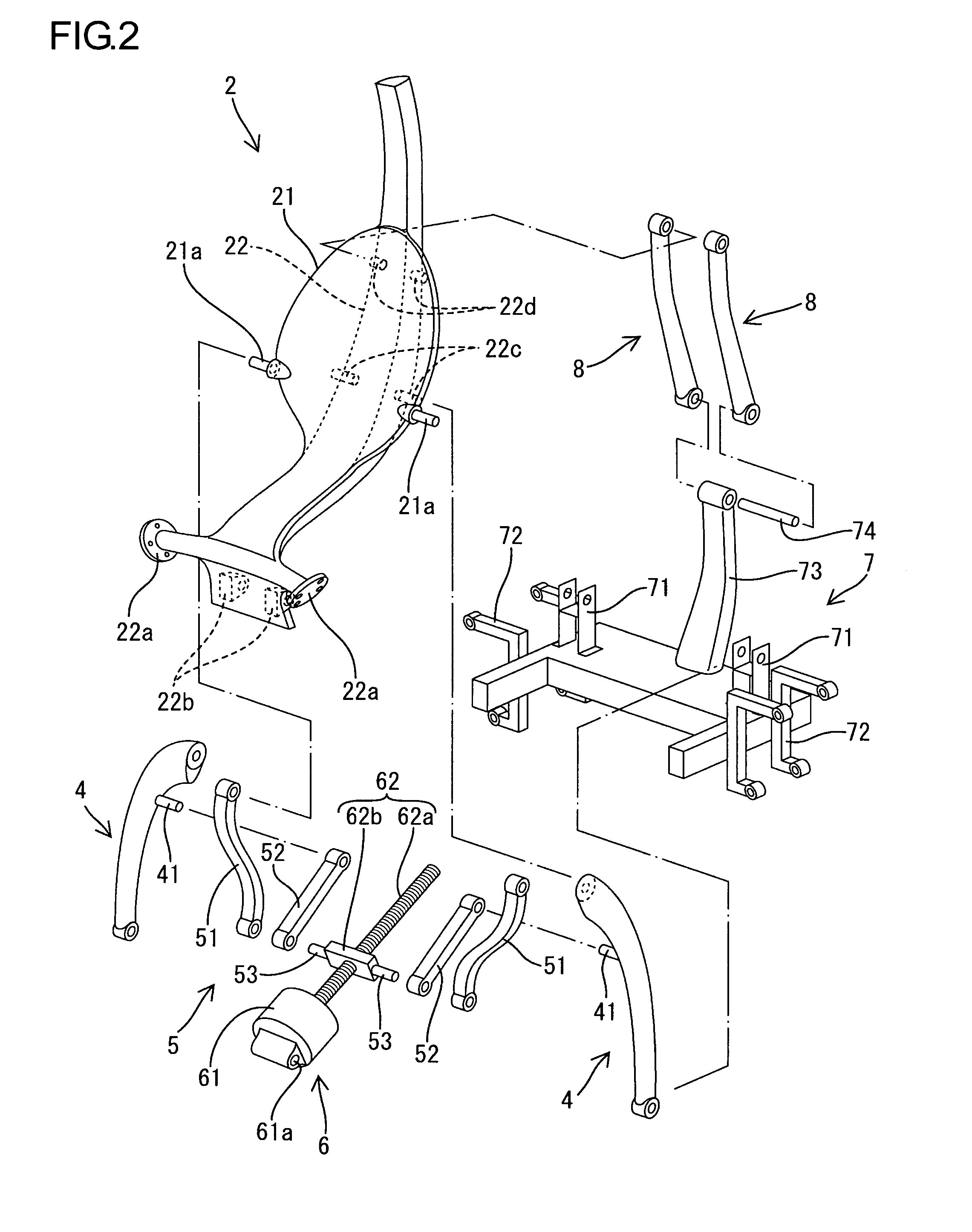
[0035]An illustrative example of the present invention is explained with reference to FIG. 1 through FIG. 4. For the following explanation, in FIG. 3 and FIG. 4, the left side is the front of the vehicle 1. The vehicle 1 having an adjustable wheel base is provided with a main frame 2. The main frame 2 is integrally formed by aluminum casting and extends in a longitudinal direction. A cavity shaped seat mounting portion 21, in which the vehicle seat SV is mounted, is formed at the center portion of the main frame 2. A frame structure 22 is formed on the back surface of the seat mounting portion 21, extends so as to curve in a vertical direction with respect to the seat mounting portion 21, and supports the vehicle seat SV. The vehicle seat SV is formed in a shape that accommodates and supports the body of a seated driver and a step ST is provided on a lower end portion thereof for a seated driver to use during ingress and egress (shown in FIG. 1).

[0036]On the front portion of the mai...


PUM


Abstract

The front wheels of the vehicle having an adjustable wheel base are joined to the front portion of a main frame, on which a vehicle seat is mounted. The upper ends of a pair of rotating arms are rotatably joined to the main frame. The lower ends of the rotating arms are rotatably joined to the rear wheels. The upper arms and the lower arm are provided rotatably connected together such that the main frame and the rear wheels are joined at the back of the rotating arms. The operating portion of the operating apparatus, on which the main frame is installed, is joined via the operating links to the rotating arms. By operating the operating apparatus, the rotating arms are rotated by the operating links and the rear wheels are moved with respect to the front wheels. Simultaneously, the inclination of the main frame is changed.

Description

TECHNICAL FIELD[0001]The present invention relates to a vehicle having an adjustable wheel base that enables the changing of the inclination of a vehicle seat in cooperation with a change in the wheel base.BACKGROUND ART[0002]There is conventional technology related to vehicles that enables the changing of a wheel base (the distance between the center of a front wheel and that of a rear wheel) depending on the traveling conditions thereof (for example, refer to Patent Document 1). In this vehicle, the rear vehicle axle is moved longitudinally by using an actuator that is attached to the vehicle frame. However, a vehicle can be considered from the point of view of vehicle stability when traveling at a high speed in which, in addition to this structure, the inclination of the vehicle seat is changed in cooperation with a change of the wheel base. Up until the present, however, there has been no proposal related to a specific structure for linking the change in the wheel base with the ...

Claims


Application Information

Patent Timeline
Patent Type & Authority Applications(United States)
IPC IPC(8): B60B35/10B62D21/14B62D31/00B62D39/00B62D63/02B62K15/00B62K17/00
CPCB60G2300/40B62D21/14B62K17/00B62K5/01B62K15/00B62D31/006
Inventor NAKAIZUMI, YASUSHIKAYUKAWA, HIROSHI
Owner TOYOTA SHATAI KK
Why Eureka
Try Eureka