Air deflecting system for automobiles

a technology for automobiles and deflectors, applied in the direction of roofs, transportation and packaging, vehicle arrangements, etc., can solve the problems of reducing the ability of the inside tires, and reducing the aerodynamic stability of the vehicle, so as to achieve greater aerodynamic stability

Inactive Publication Date: 2008-05-22
NAT ASSOC FOR STOCK CAR AUTO RACING
View PDF21 Cites 33 Cited by
  • Summary
  • Abstract
  • Description
  • Claims
  • Application Information

AI Technical Summary

Benefits of technology

[0016]The present invention provides an improved automobile design having greater aerodynamic stability during high speed cornering. Various embodiments of the present invention are particularly applicab

Problems solved by technology

This rolling moment 302 is usually undesirable in that it makes the vehicle more prone to a rollover and also reduces the weight or downward pressure on the inside tires 303 thereby reducing the ability of the inside tires 303 to grip the road.
In high speed racing applications, the combination of the negative yawing moment 308 and the automobile's inertia may exceed the tires' ability to grip the surface of the road resulting in a slide or a “spin-out” of the racecar.
For example, if the magnitude of the side force 306 required of the rear tires 304 is greater than the side force that the rear tires 304 can withstand, the rear of the vehicle will slide tow

Method used


Image

  • Air deflecting system for automobiles
  • Air deflecting system for automobiles
  • Air deflecting system for automobiles

Examples


Embodiment Construction

[0042]The present invention now will be described more fully hereinafter with reference to the accompanying drawings, in which some, but not all embodiments of the invention are shown. Indeed, the invention may be embodied in many different forms and should not be construed as limited to the embodiments set forth herein; rather, these embodiments are provided so that this disclosure will satisfy applicable legal requirements. Like numbers refer to like elements throughout.

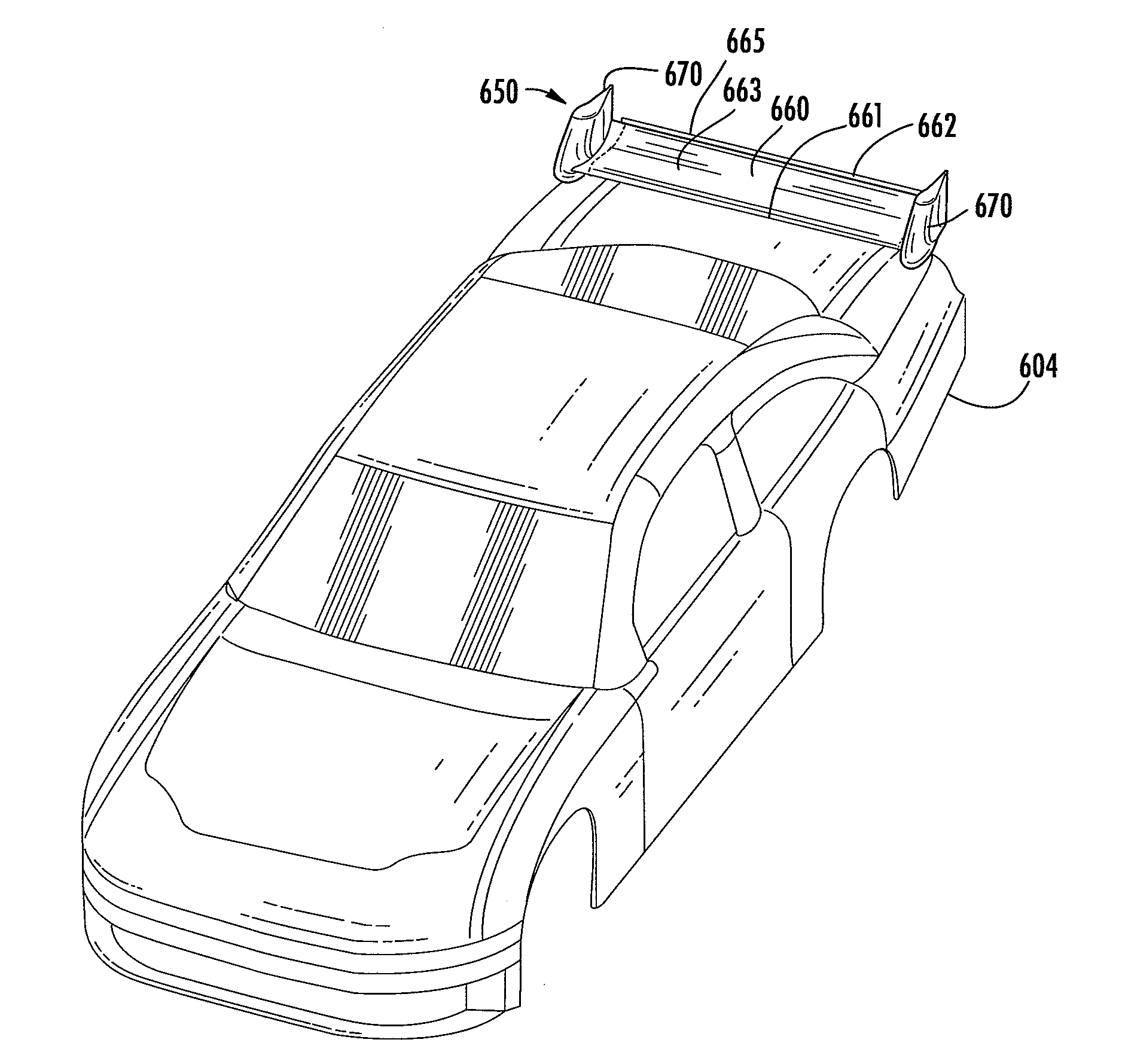
[0043]FIG. 4 depicts an air deflecting system 450 attached to an automobile 400 in accordance with one embodiment of the invention. As will be discussed in greater detail below, air deflecting systems structured according to various embodiments of the present invention may produce a number of desirable effects including an increased side force 451, a more favorable yawing moment 452, and / or a more favorable rolling moment (not shown) about the automobile's CG when the automobile is cornering or is otherwise yawed b...


PUM


Abstract

Various embodiments of the present invention are directed to an air deflecting system positioned on an automobile and configured to produce an increased side force and/or a more favorable yawing moment when the automobile is cornering or is otherwise yawed relative to the direction of the free stream air flow. In one exemplary embodiment, the deflecting system comprises a downforce-producing horizontal rear wing located proximate the rear end of the automobile, the rear wing having an endplate on each end. In one embodiment, the endplates are angled or have cambered airfoil cross-sections such that they each generate an aerodynamic force towards the inside of a turn when the automobile is cornering.

Description

FIELD OF THE INVENTION[0001]The present invention relates generally to automobile aerodynamics, and more particularly to an air deflector positioned on an automobile and configured to produce aerodynamic forces that favorably affect the forces on an automobile during cornering or when otherwise yawed.BACKGROUND OF THE INVENTION[0002]Aerodynamic forces are commonly used by automotive engineers to enhance automobile performance, safety, and fuel economy. Engineers shape the body contour of an automobile to create and enhance certain aerodynamic forces. In one example, many racing and high-performance automobiles are equipped with rear spoilers that produce downforce or “negative lift” proximate the rear end of the vehicle. Such downforce improves the automobile's traction or ability to hold the road. However, in addition to adding desirable downforce, rear spoilers sometimes add performance-reducing drag to the automobile. This trade-off effectively illustrates the need for automotive...

Claims


Application Information

Patent Timeline
IPC IPC(8): B60J1/20
CPCB62D37/02B62D35/007Y02T10/82
Inventor HONEYCUTT, DANIEL BARRY
Owner NAT ASSOC FOR STOCK CAR AUTO RACING
Why Eureka
Try Eureka