
Light source apparatus, backlight apparatus, liquid crystal display apparatus, and manufacturing method of backlight apparatus

a technology of liquid crystal display and backlight, which is applied in the direction of lighting and heating apparatus, lighting support devices, instruments, etc., can solve the problems of large reduction in the flexibility of selecting respective leds, uneven color and uneven luminance, and sometimes still occur without accommodating variations, so as to increase the flexibility of selecting leds and increase the chromaticity and luminance uniformity

Active Publication Date: 2008-05-22
SATURN LICENSING LLC
View PDF3 Cites 35 Cited by
  • Summary
  • Abstract
  • Description
  • Claims
  • Application Information

AI Technical Summary

Benefits of technology

[0013]In view of the above circumstances, it is desirable to provide a light source apparatus capable of increasing chromaticity and luminance uniformities by increasing the flexibility of selection of LEDs of respective colors, a backlight apparatus equipped with this light source apparatus, a liquid crystal display apparatus equipped with this backlight apparatus, and a manufacturing method of this backlight apparatus.
[0040]As described above, according to the embodiments of the present invention, by increasing the flexibility of selection of LEDs of respective colors, chromaticity and luminance uniformities can be increased.

Problems solved by technology

However, in the techniques described in the above respective Patent Documents, the LEDs of respective colors in the unit are not allowed to be replaced, so that it is necessary to adjust the variations in chromaticity and luminance on a unit-by-unit basis, leading to a great reduction in the flexibility of selection of respective LEDs.
As a result, uneven color and uneven luminance sometimes still occur without accommodating the variations in chromaticity and luminance.

Method used


Image

  • Light source apparatus, backlight apparatus, liquid crystal display apparatus, and manufacturing method of backlight apparatus
  • Light source apparatus, backlight apparatus, liquid crystal display apparatus, and manufacturing method of backlight apparatus
  • Light source apparatus, backlight apparatus, liquid crystal display apparatus, and manufacturing method of backlight apparatus

Examples


Embodiment Construction

[0053]An embodiment of the present invention will be described below with reference to the drawings.

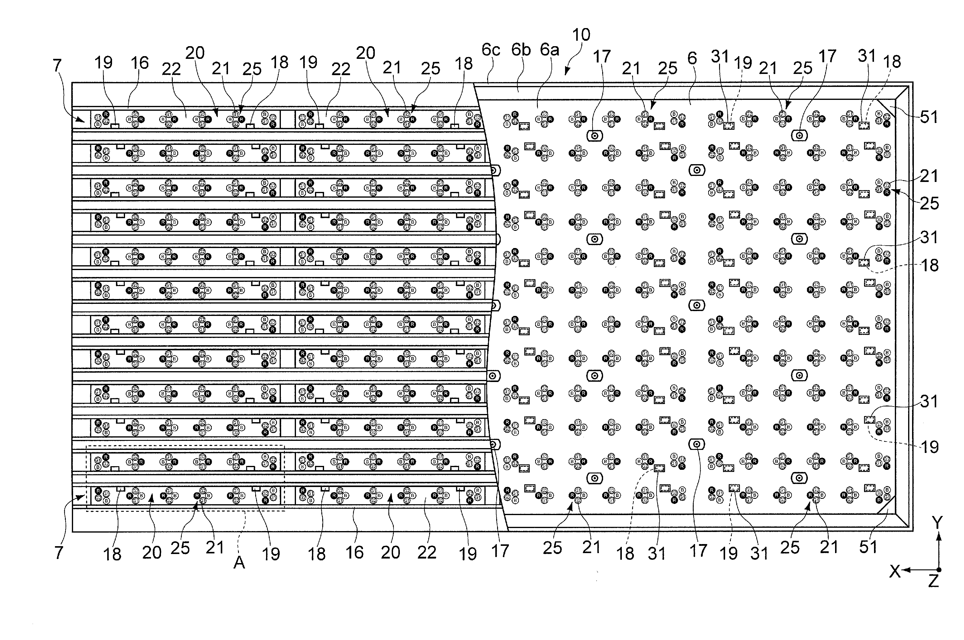
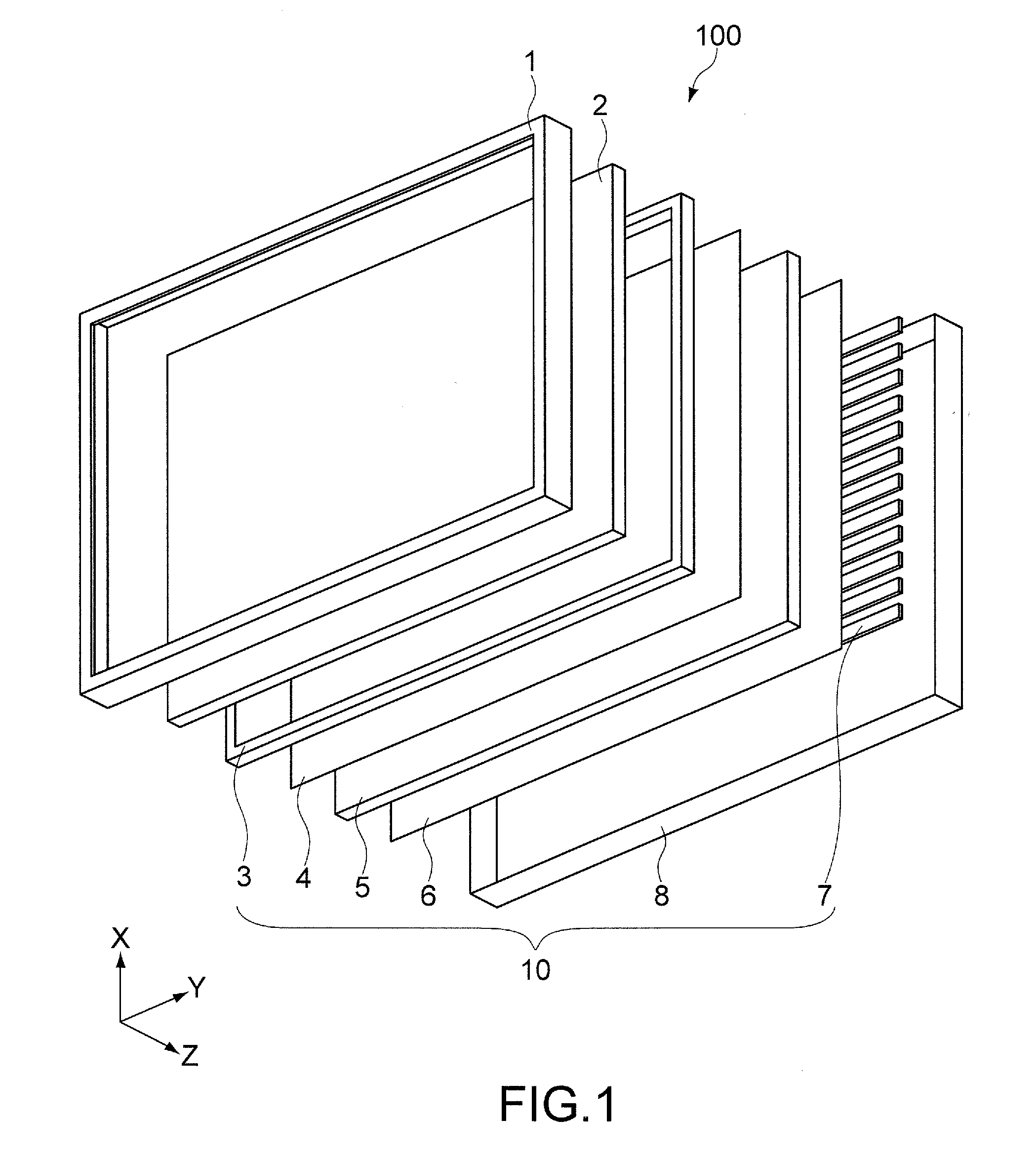
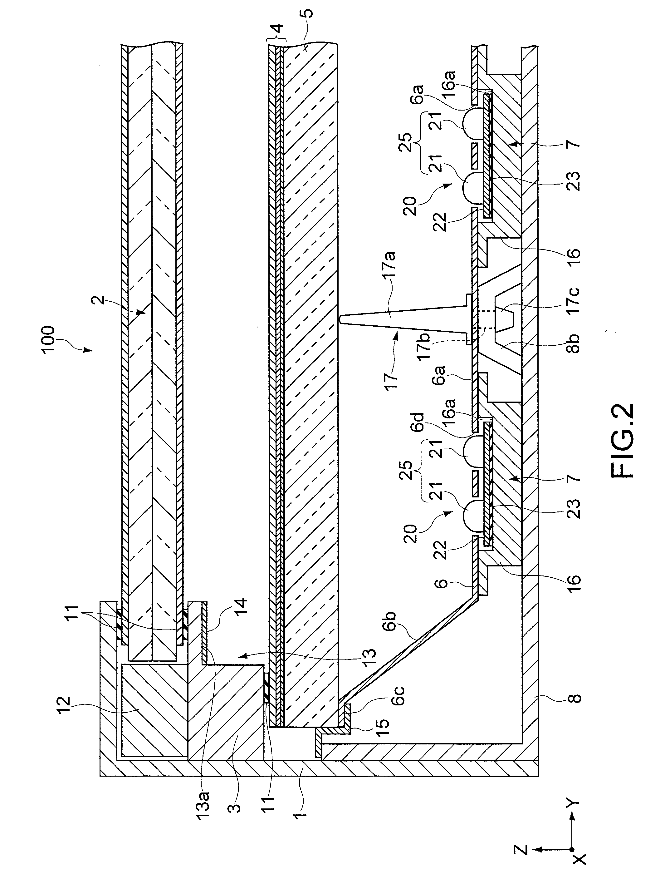
[0054]FIG. 1 is a schematic exploded perspective view of a liquid crystal display apparatus including a backlight apparatus according to the embodiment of the present invention. FIG. 2 is a partial sectional view in a Z direction of the liquid crystal display apparatus shown in FIG. 1. FIG. 3 is a partial cutaway plan view showing the structure of the backlight apparatus of the liquid crystal display apparatus shown in FIG. 1 and FIG. 2.

[0055]This liquid crystal display apparatus is used, for example, for a display panel of a television receiver having a large display screen of 40 inches or more, and is a transmissive liquid crystal display apparatus which displays an image by illuminating a liquid crystal panel from the back surface side with the backlight apparatus.

[0056]As shown in FIG. 1 and FIG. 2, a liquid crystal display apparatus 100 is constituted by sandwiching and holding a...


PUM


Abstract

A light source apparatus used in a backlight apparatus is disclosed. The light source apparatus includes a light-emitting diode unit and a wiring board. The light-emitting diode unit is provided as one unit by nonlinearly and closely placing respective light-emitting diodes of red, green, and blue colors, at least the light-emitting diode of one color out of the light-emitting diodes of the respective colors being constituted by first and second light-emitting diodes having different chromaticities such that an average chromaticity of the first and second light-emitting diodes is a predetermined chromaticity. On the wiring board, a plurality of light-emitting diode units are arranged at predetermined intervals in a predetermined direction.

Description

CROSS REFERENCES TO RELATED APPLICATIONS[0001]The present invention contains subject matter related to Japanese Patent Application JP 2006-314640 filed in the Japanese Patent Office on Nov. 21, 2006, the entire contents of which being incorporated herein by reference.BACKGROUND OF THE INVENTION[0002]1. Field of the Invention[0003]The present invention relates to a light source apparatus using an LED (Light-emitting Diode), a backlight apparatus equipped with the light source apparatus, a liquid crystal display apparatus equipped with the backlight apparatus, and a manufacturing method of the backlight apparatus.[0004]2. Description of the Related Art[0005]In the past, in an LCD (Liquid Crystal Display) mounted in an electronic apparatus such as a liquid crystal television, a PC (Personal Computer), or the like, an image has been displayed by placing a backlight on the back surface side of the LCD and illuminating the back surface of the LCD with the backlight. As a light source of t...

Claims


Application Information

Patent Timeline
IPC IPC(8): G02F1/1335F21S13/14H01L33/60
CPCG02F1/133603G02F2001/133613G02F1/133609G02F1/133613G02F1/1335G02F1/133
Inventor OKU, TAKASHIKOBAYASHI, NAOTOUBA, TOMOHISA
Owner SATURN LICENSING LLC
Learn More