Wind Turbine Comprising a Multiplied Redundancy Control System and Method of Controlling a Wind Turbine

a control system and wind turbine technology, applied in the field of wind turbines, can solve the problems of more than one component of a kind not changing or solving, increasing the challenge of transporting and handling the components of large modern wind turbines, and increasing the difficulty of controlling the components of large wind turbines. achieve the effect of enhancing the facilitating the positioning of controllers, and enhancing the high reliability of the control system

Active Publication Date: 2008-05-22
VESTAS WIND SYST AS
View PDF8 Cites 51 Cited by
  • Summary
  • Abstract
  • Description
  • Claims
  • Application Information

AI Technical Summary

Benefits of technology

[0008]Hereby is established a wind turbine without the above-mentioned disadvantages of the prior art. The elimination of single points of failure possibility in the control of equipment under control by securing the functionality on system level is advantageous. With the enhancing of the safety level and thus the reliability of the wind turbine it is possible to design the different wind turbine components to normal use and fatigue instead of designing for extreme loads.
[0033]In an aspect of the invention, said controllers are distributed at the wind turbine hub, the main shaft, the root of the wind turbine blade and / or inside the blade. By positioning the controllers locally in proximity of the equipment under control a simpler and more reliable construction of a control arrangement is achieved.

Problems solved by technology

However, it is an increasing challenge to transport and handle the wind turbine components of large modern wind turbines.
Consequently, the over-sized components are a significant problem in relation to size and weight during transport and handling as well as expensive in material costs.
However, the more than one component of a kind does not change or solve the above-mentioned problem regarding size and weight as well as material costs of wind turbine components.

Method used


Image

  • Wind Turbine Comprising a Multiplied Redundancy Control System and Method of Controlling a Wind Turbine
  • Wind Turbine Comprising a Multiplied Redundancy Control System and Method of Controlling a Wind Turbine
  • Wind Turbine Comprising a Multiplied Redundancy Control System and Method of Controlling a Wind Turbine

Examples


Embodiment Construction

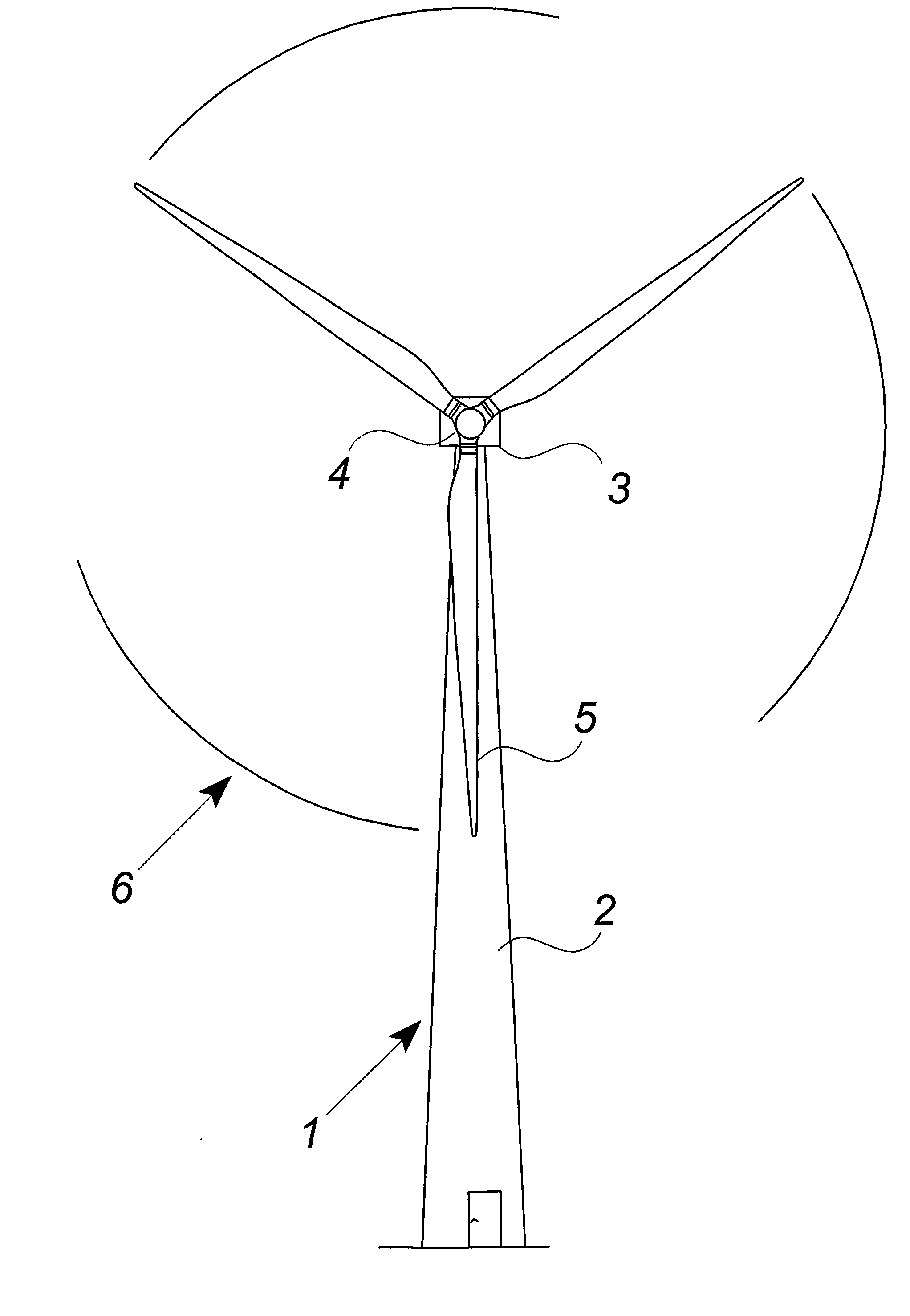
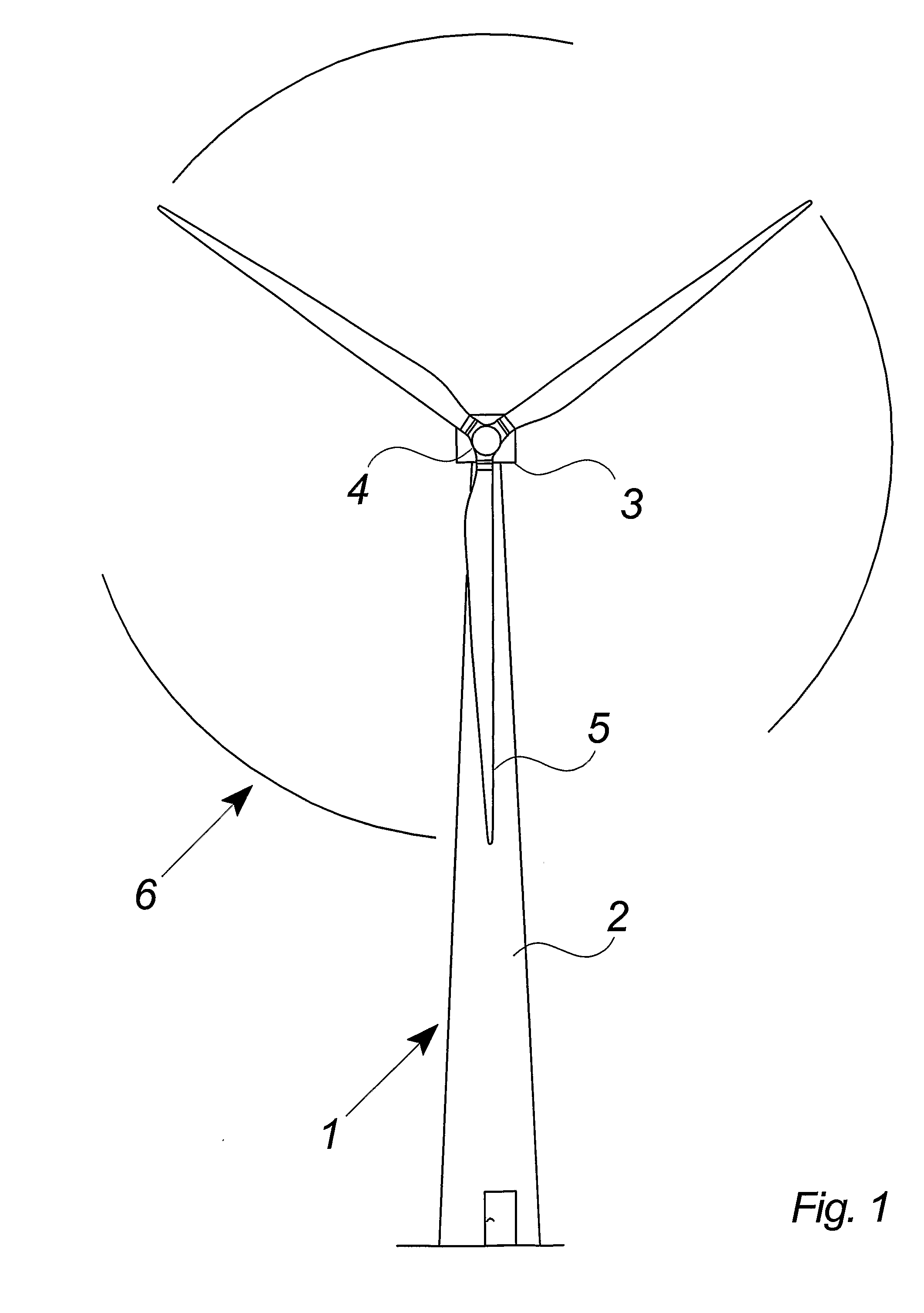
[0047]FIG. 1 illustrates a modern wind turbine 1 with a tower 2 and a wind turbine nacelle 3 positioned on top of the tower. The blades 5 of the wind turbine rotor are connected to the nacelle through the low speed shaft which extends out of the nacelle front.

[0048]As illustrated in the figure, wind over a certain level will activate the rotor and allow it to rotate in a perpendicular direction to the wind. The rotation movement is converted to electric power which usually is supplied to the transmission grid as will be known by skilled persons within the area.

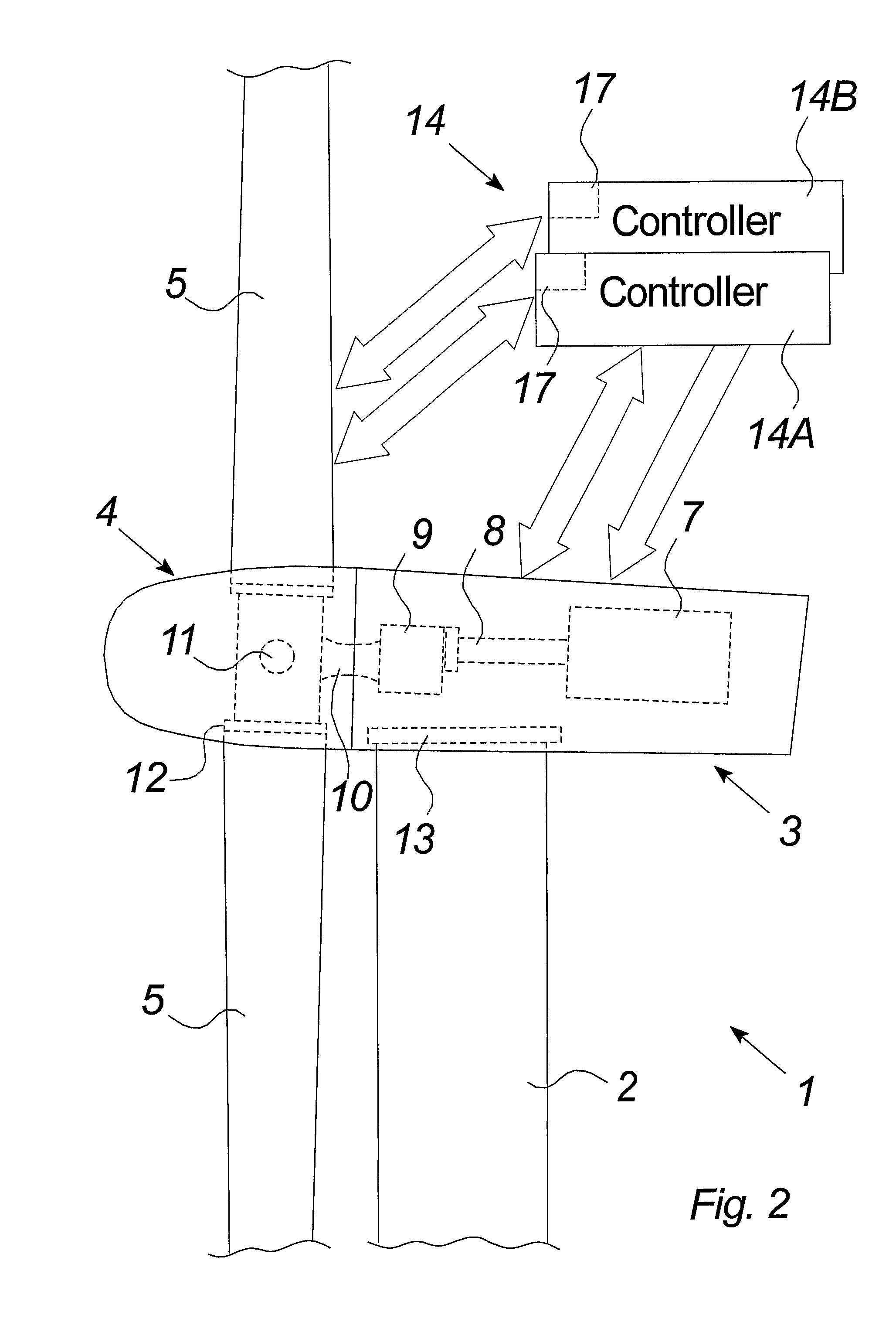
[0049]FIG. 2 illustrates schematically the equipment under control, i.e. the wind turbine blades 5, the gear 9, and the electric generator 7. The equipment under control are supervised and controlled by control systems 14 of a wind turbine according to the invention. The wind turbine further comprises the low and high speed shafts 10, 8 connecting the wind turbine blades 5, the gear 9, and the electric generator 7. Teeter mech...


PUM


Abstract

A wind turbine (1) comprising equipment under control is presented, which comprises at least one control system (14, 14A, 14B) for one or more of said main components, (5, 7, 9) of the wind turbine. The control system (14A) is multiplied by at least one further control system (14B) for controlling the same of said equipment under control. A control arrangement, a method as well as uses hereof are also presented.

Description

BACKGROUND OF THE INVENTION[0001]The invention relates to a wind turbine according to the preamble of claim 1, a control arrangement, a method of controlling a control system being multiplied by at least one further control system for controlling the same equipment under control of a wind turbine and uses hereof.DESCRIPTION OF THE RELATED ART[0002]Wind turbines are designed to face harsh and changing weather in a long period of years and still show a high dependability. Previously, the dependability has been achieved by designing wind turbines with a certain over-sizing in relation to the required under normal use of the wind turbine.[0003]The tower, wind turbine blades and breaking systems may for example be over-sized in order to handle extreme weather situation or excessive forces during a malfunction such as loss of utility grid or control of the wind turbine rotor.[0004]However, it is an increasing challenge to transport and handle the wind turbine components of large modern wi...

Claims


Application Information

Patent Timeline
Patent Type & Authority Applications(United States)
IPC IPC(8): F03D7/04
CPCF03D7/0224F03D7/047Y02E10/723F05B2270/1074F05B2260/845Y02E10/72
Inventor JEPPESEN, OLE MOLGAARDBENGTON, JOHNHANSEN, TORBEN MOLLER
Owner VESTAS WIND SYST AS
Why Eureka
Try Eureka