Connector and a connector assembly

a technology of connectors and components, applied in the direction of coupling device connections, coupling parts engagement/disengagement, electrical apparatus, etc., to achieve the effect of preventing separation, improving assembly operability, and efficiently separated

Inactive Publication Date: 2008-05-22
SUMITOMO WIRING SYST LTD
View PDF5 Cites 7 Cited by
  • Summary
  • Abstract
  • Description
  • Claims
  • Application Information

AI Technical Summary

Benefits of technology

[0012]Two locking projections preferably project out from the outer peripheral surface of the wall of the terminal protection plate and are engageable with the engaging grooves. Stoppers are formed near the front ends of the engaging grooves and engage the locking projections to prevent separation of the terminal protection plate from the receptacle.
[0013]The locking projections engage the front end edges of the engaging grooves to limit movement of the male terminal protection plate in the separating direction. Additionally, the two locking projections and the two engaging grooves are arranged at opposite sides of the cam pin in directions normal to the moving directions of the male terminal protection plate. Thus, the male terminal protection plate cannot incline about the cam pins. Accordingly, the female housing will not interfere with the receptacle due to the inclination of the male terminal protection plate, and the female housing can be separated efficiently from the receptacle. Further, the male terminal protection plate and the female housing can be moved smoothly in the connecting and separating directions without causing any wrenching movement.
[0014]The one or more locking projections preferably are formed on one or more resilient locking pieces displaceable inward relative to the wall. Thus, the resilient locking pieces are deformed resiliently inward upon mounting the male terminal protection plate into the receptacle. As a result, the locking projections can pass the stoppers to engage with the engaging grooves, and assembling operability can be improved.
[0015]The resilient locking pieces preferably are cantilevered in the separating direction of the mating housing from the receptacle. Additionally, the extending ends of the locking projections preferably are exposed at the front edge of the wall. Thus, an opening direction of a mold for forming the resilient locking pieces can be the same as the direction from the rear end toward the front end of the surrounding wall, i.e. an opening direction of a mold for forming the surrounding wall. A mold that is opened in a normal to the surface of the surrounding wall can be eliminated and a cost for molds can be reduced.

Problems solved by technology

The male terminal protection plate might incline together with the female housing upon separating the female housing from the male housing, and the female housing might interfere with the receptacle to hinder the separating operation due to this inclination.

Method used


Image

  • Connector and a connector assembly
  • Connector and a connector assembly
  • Connector and a connector assembly

Examples


Embodiment Construction

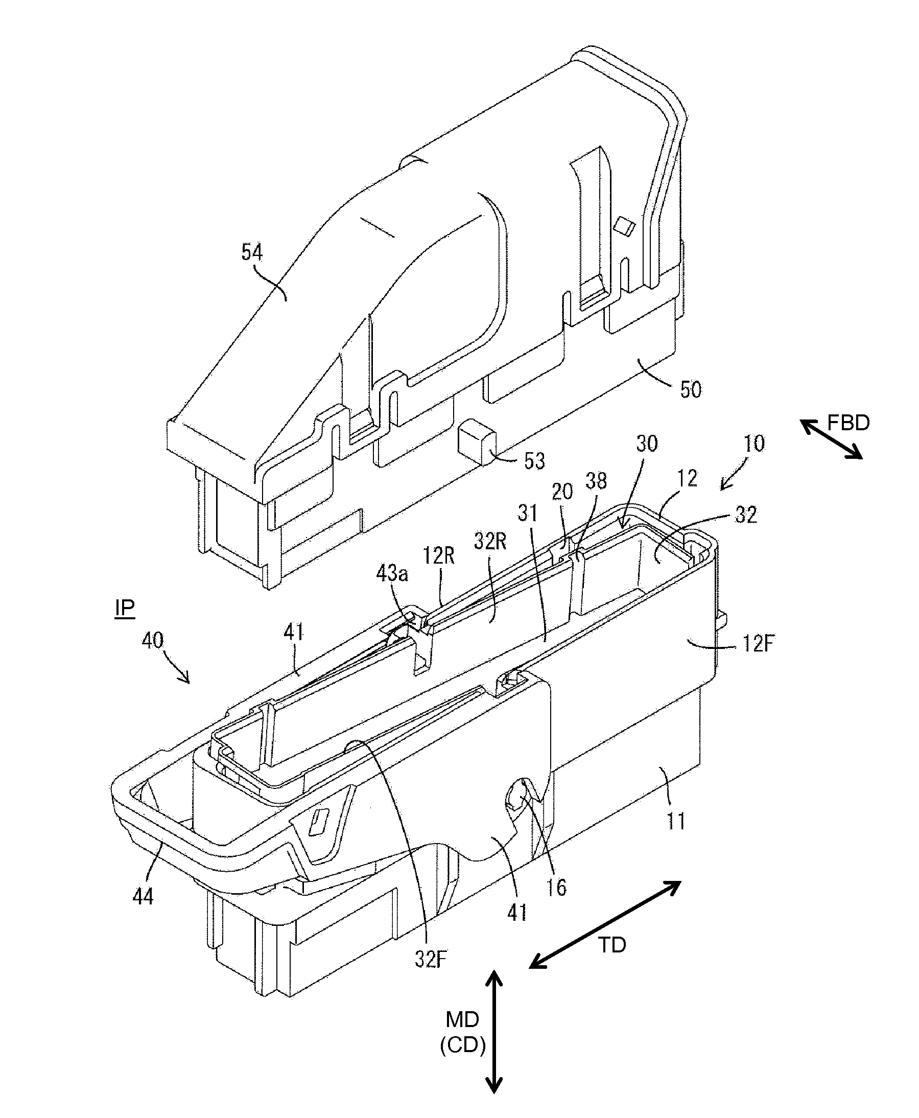
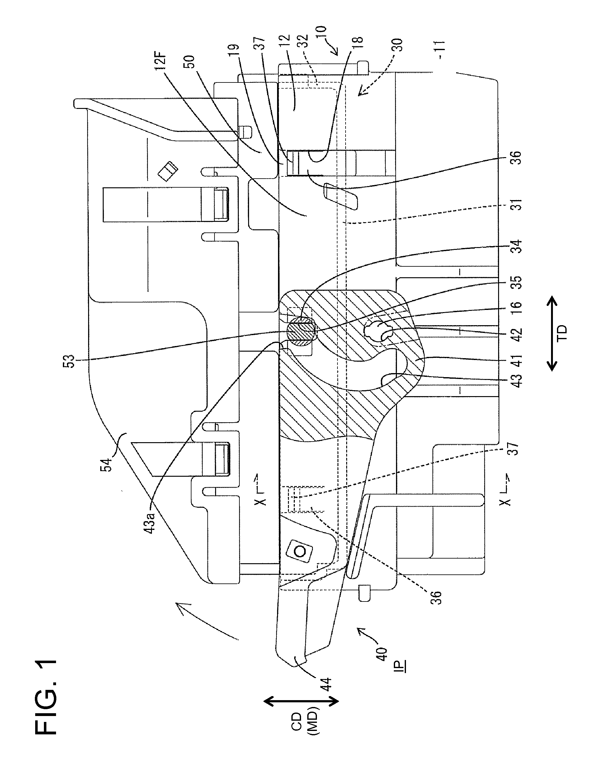
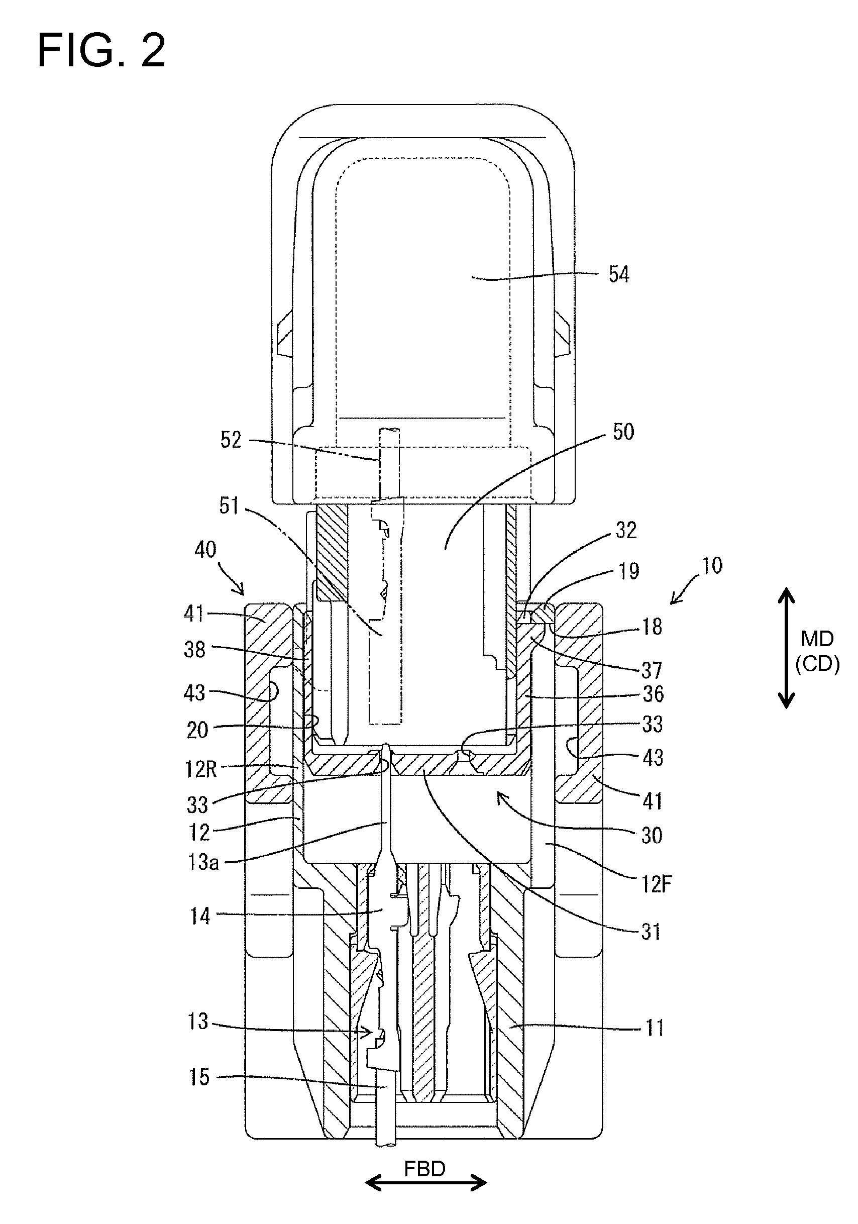
[0030]A connector in accordance with the invention is illustrated in FIGS. 1 to 9 and includes male and female housings 10 and 50 that are connected and separated along a connecting direction CD. The end of the male housing 10 that faces up in the FIGS. 1 through 5, 7 and 9 is referred to herein as the front end, and defines the end that is connectable with the female housing 50.

[0031]The male housing 10 is made e.g. of a synthetic resin and includes a terminal holding portion 11 in the form of a block that is long and narrow in the transverse direction TD. A rectangular tubular receptacle 12 projects up and forward from the peripheral edge of the terminal holding portion 11. Terminal fittings 13 are arranged in the transverse direction TD and have main portions 14 accommodated in the terminal holding portion 11. Each terminal fitting 13 is aligned in forward and backward directions FBD. Wires 15 are secured to the bottom ends of the terminal main bodies 14 and are drawn out from a ...


PUM


Abstract

A male terminal protection plate (30) is moved together with a female housing (50) in a direction separating from a receptacle (12), any further movement of the male terminal protection plate (30) in the separating direction can be prevented when a pair of locking projections (37) come into engagement with the upper edges of a pair of engaging grooves (18). Since the pair of locking projections (37) and the pair of engaging grooves (18) are arranged at the opposite sides of a cam pin (34), about which the male terminal protection plate (30) could be inclined, in a direction normal to moving directions of the male terminal protection plate (30), the inclination of the male terminal protection plate (30) can be prevented.

Description

BACKGROUND OF THE INVENTION[0001]1. Field of the Invention[0002]The invention relates to a connector with a male terminal protection plate.[0003]2. Description of the Related Art[0004]U.S. Patent Application Publication No. 2006 / 0154505 discloses a connector with a male terminal protection plate. The male terminal protection plate has a surrounding wall accommodated in a receptacle of a male housing and tabs of male terminal fittings are positioned by the male terminal protection plate. A lever is mounted on the male housing and is formed with cam grooves. Cam pins project from the surrounding wall of the male terminal protection plate and can be united with cam followers of the mating female housing. The cam pins and the cam followers can be received in the cam grooves of the lever. The lever then is rotated to pull the female housing and the male terminal protection plate into the receptacle for connecting the male and female housings.[0005]A connector with a male terminal protect...

Claims


Application Information

Patent Timeline
Patent Type & Authority Applications(United States)
IPC IPC(8): H01R13/44
CPCH01R13/62938H01R13/4538H01R13/639
Inventor OKANO, TOMOKI
Owner SUMITOMO WIRING SYST LTD
Why Eureka
Try Eureka