Knee joint prosthesis for bi-compartmental knee replacement and surgical devices thereof

Inactive Publication Date: 2008-05-22
OH SANG SOO
View PDF7 Cites 117 Cited by
  • Summary
  • Abstract
  • Description
  • Claims
  • Application Information

AI Technical Summary

Benefits of technology

[0011]The present invention provides a knee joint prosthesis for a bi-compartmental knee replacement performed on a patient with degenerative arthritis at any one of an inside compartment and an outside compartment of the knee and between the femur and the patella, in which a femoral component is positioned at any one of an inside and an outside of the femur of the patient, a front part and the entire front corner part; a tibial component is positioned at any one of an inside and an outside of the tibia of the patient; and a tibial bearing member is positioned between t

Problems solved by technology

The natural friction of the replaced artificial joint removes particles of debris (i.e., metals or plastics separated from the prosthesis), thereby increasing the wear debris moving in the joint.
The wear debris of the artificial joint interrupts a proper mechanical function of the artificial joint.
Moreover, the wear debris may cause a bone to be broken and damaged.
Accordingly, soft tissues are damaged and blood loss increases.
Moreover, the prosthesis used for the total knee replacement has the difficult in adjusting the flexion-extension gap and the ligament balance upon the total knee replacement surgery, compared to the uni-compartmental knee replacement surgery performed without removing the other normal compartments.
As a result, the prosthesis is likely to be misaligned and shaken, and the use life of the prosthesis is shortened.
However, the prosthesis for the uni-compartmental knee replacement is weak in a securing force.
Moreover, the pr

Method used


Image

  • Knee joint prosthesis for bi-compartmental knee replacement and surgical devices thereof
  • Knee joint prosthesis for bi-compartmental knee replacement and surgical devices thereof
  • Knee joint prosthesis for bi-compartmental knee replacement and surgical devices thereof

Examples


Example

[0038]The present invention will now be described more fully hereinafter with reference to the accompanying drawings, in which preferred embodiments of the invention are shown. This invention may, however, be embodied in many different forms and should not be construed as being limited to the embodiments set forth herein. Rather, these embodiments are provided so that this disclosure will be thorough and complete, and will fully convey the scope of the invention to those skilled in the art.

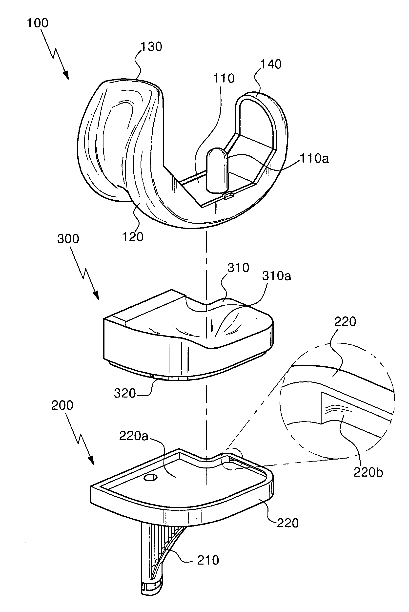
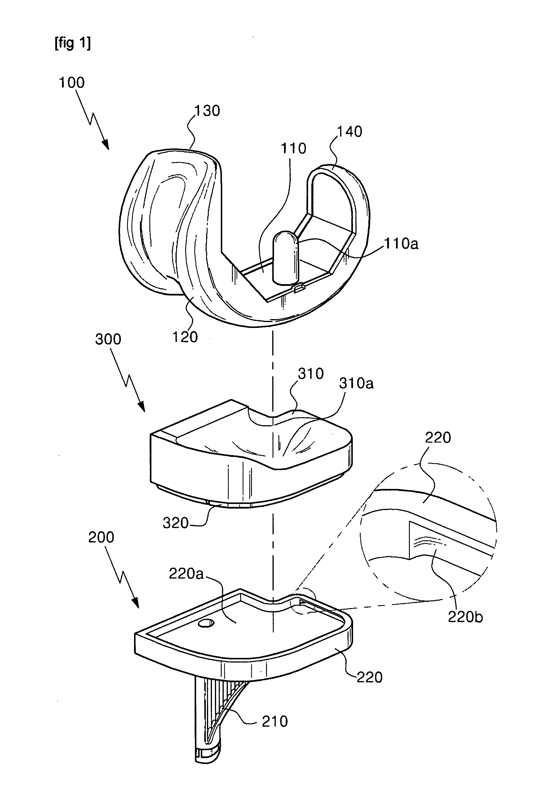
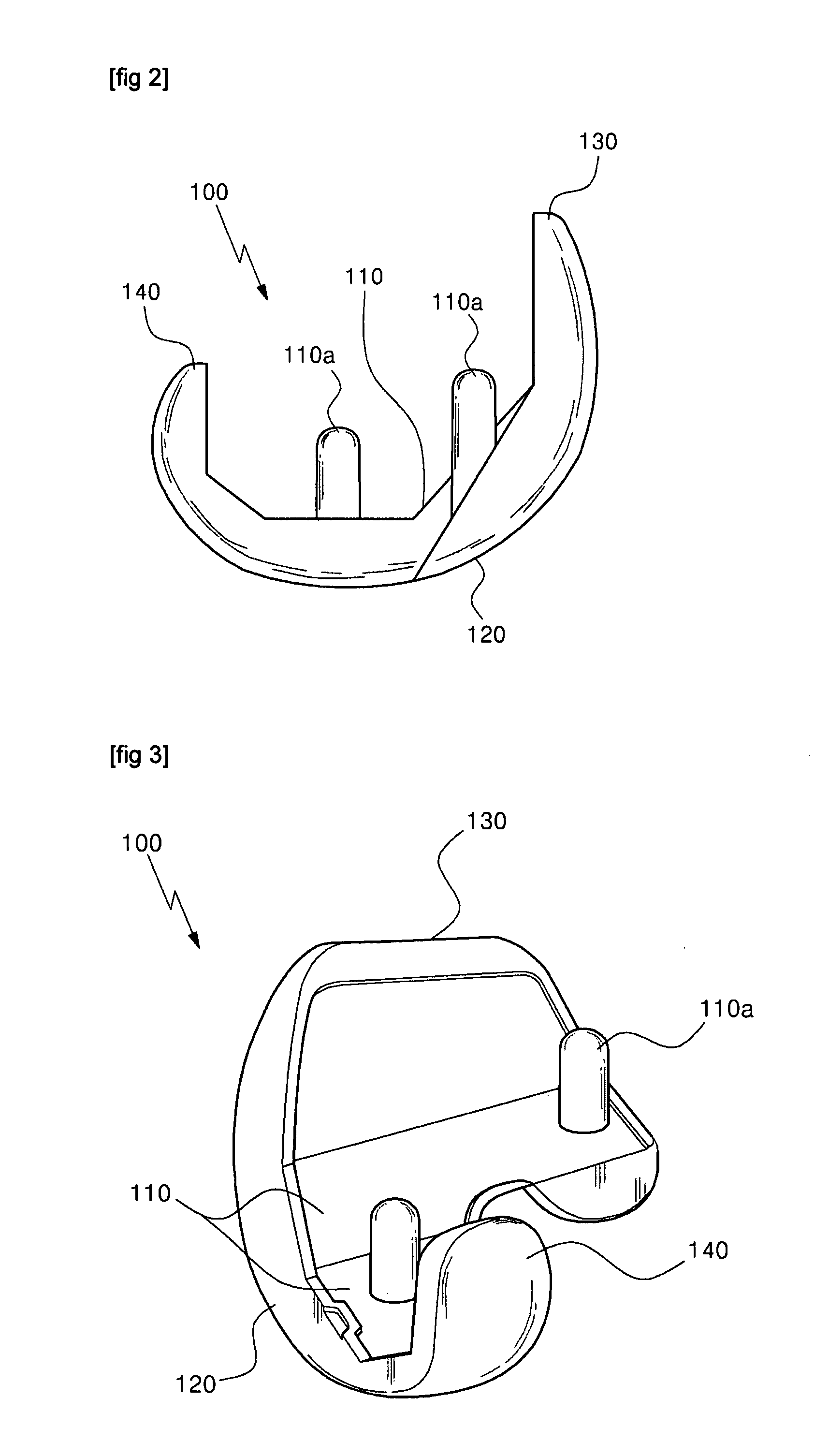
[0039]FIG. 1 is a dissembled perspective view of a knee joint prosthesis for a bi-compartmental replacement according to an embodiment of the present invention, FIG. 2 is a side view of a femoral component of FIG. 1, FIG. 3 is a perspective view of the femoral component of FIG. 1, FIG. 4 is a side view of a tibial component of FIG. 1, FIG. 5 is a side view of a tibial bearing member of FIG. 1, FIG. 6 is a plan view of a femoral sizer according to an embodiment of the present invention, FIG. 7 is a...


PUM


Abstract

There are provided a knee joint prosthesis for a bi-compartmental knee replacement and surgical devices thereof, wherein the knee joint prosthesis for the bi-compartmental knee replacement, which is performed on a patient with degenerative arthritis at any one of an inside compartment and an outside compartment of the knee and between the femur and the patella, is configured to position a femoral component at the inside or outside of the femur of the patient, to position a tibial component at the inside or outside of the tibia, and to properly position a tibial bearing member between the femoral component and the tibial component, thereby having the effects of improving the range of sense and motion after surgery by preserving other normal joints and reducing blood loss compared to a conventional prosthesis; improving the accuracy of the surgery to prevent the malalignment of the prosthesis, reduce the shaking of the prosthesis and extend the use life of the prosthesis; significantly improving a securing force compared to a conventional prosthesis; and using the knee joint prosthesis for the bi-compartmental knee replacement for patients with bi-compartmental arthritis, genu varum and genu valgum and flexion deformity, and anterior cruciate ligament loss.

Description

CROSS-REFERENCE TO RELATED PATENT APPLICATION[0001]This application claims the benefit of Korean Patent Application No. 10-2006-0113737, filed on Nov. 17, 2006 and 10-2007-0022798, filed on Mar. 8, 2007 in the Korean Intellectual Property Office, the disclosure of which is incorporated herein in its entirety by reference.BACKGROUND OF THE INVENTION[0002]1. Field of the Invention[0003]The present invention relates to a knee joint prosthesis for a bi-compartmental knee replacement and surgical devices thereof, and more particularly, to a knee joint prosthesis for a bi-compartmental knee replacement which is performed on a patient with degenerative arthritis at any one of an inside compartment and an outside compartment of the knee and between the femur and the patella, and surgical device thereof. When using the knee joint prosthesis for the bi-compartmental knee replacement, a femoral component is positioned at any one of the inside and outside of the femur of the patient, the front ...

Claims


Application Information

Patent Timeline
IPC IPC(8): A61F2/38
CPCA61B17/155A61B17/157A61B17/1604A61B17/1675A61F2/38A61F2002/3895A61F2/4684A61F2002/30604A61F2002/30878A61F2002/30884A61F2/4657
Inventor OH, SANG SOO
Owner OH SANG SOO
Why Eureka
Try Eureka