Electrical connecting apparatus

Active Publication Date: 2008-05-29
NIHON MICRONICS
View PDF3 Cites 8 Cited by
  • Summary
  • Abstract
  • Description
  • Claims
  • Application Information

AI Technical Summary

Benefits of technology

[0009]An object of the present invention is, therefore, to provide an electrical connecting apparatus capable of ensuring a connection area to a tester on one surface of a circuit board sufficiently even when upsizing of a probe board causes the probe area to stretch to an outward area of a reinforcing plate.

Problems solved by technology

This causes a problem of interference between the connector 7 and the end portion of the second vertical path portion 6b.

Method used


Image

  • Electrical connecting apparatus
  • Electrical connecting apparatus
  • Electrical connecting apparatus

Examples


Embodiment Construction

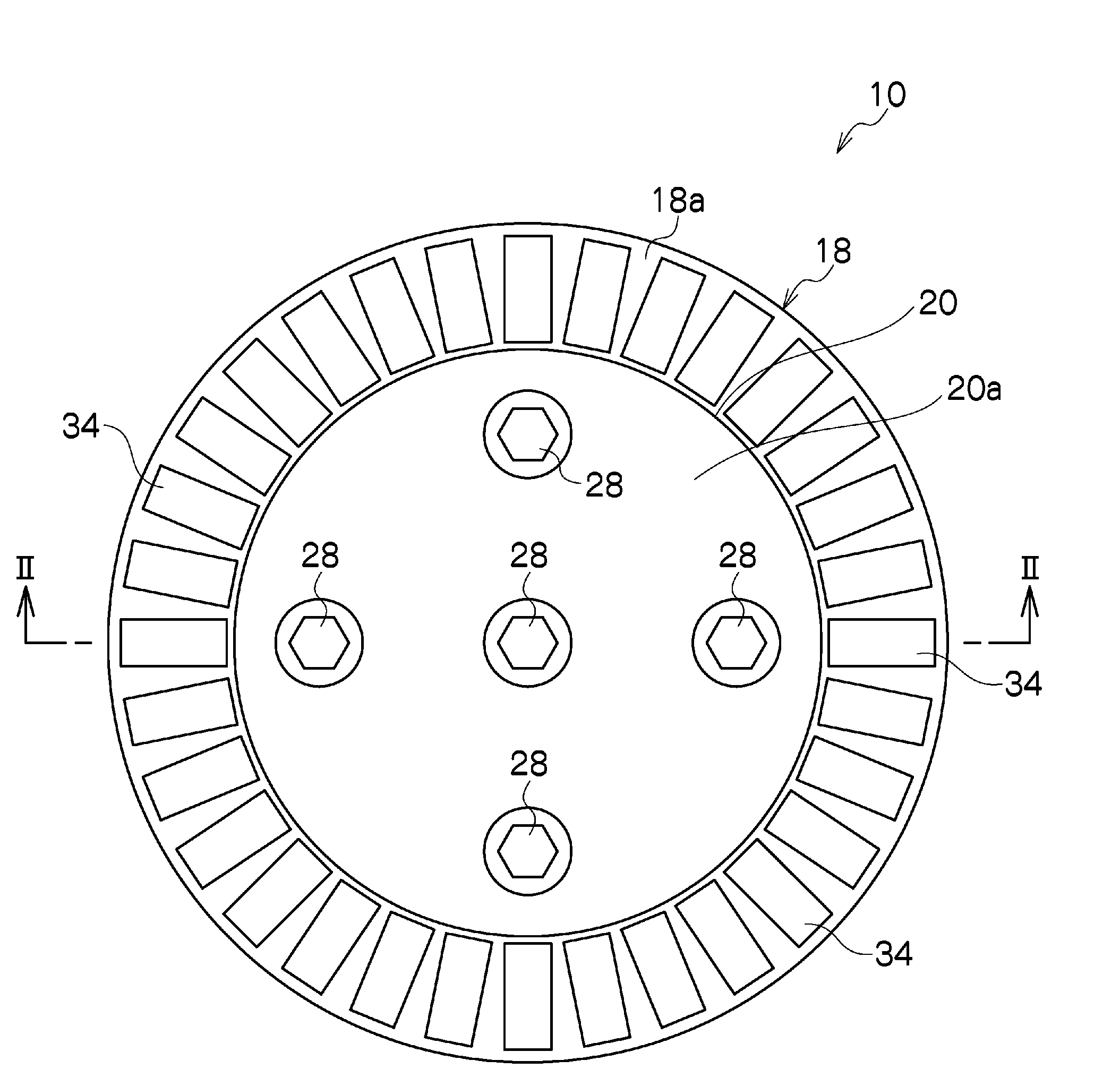
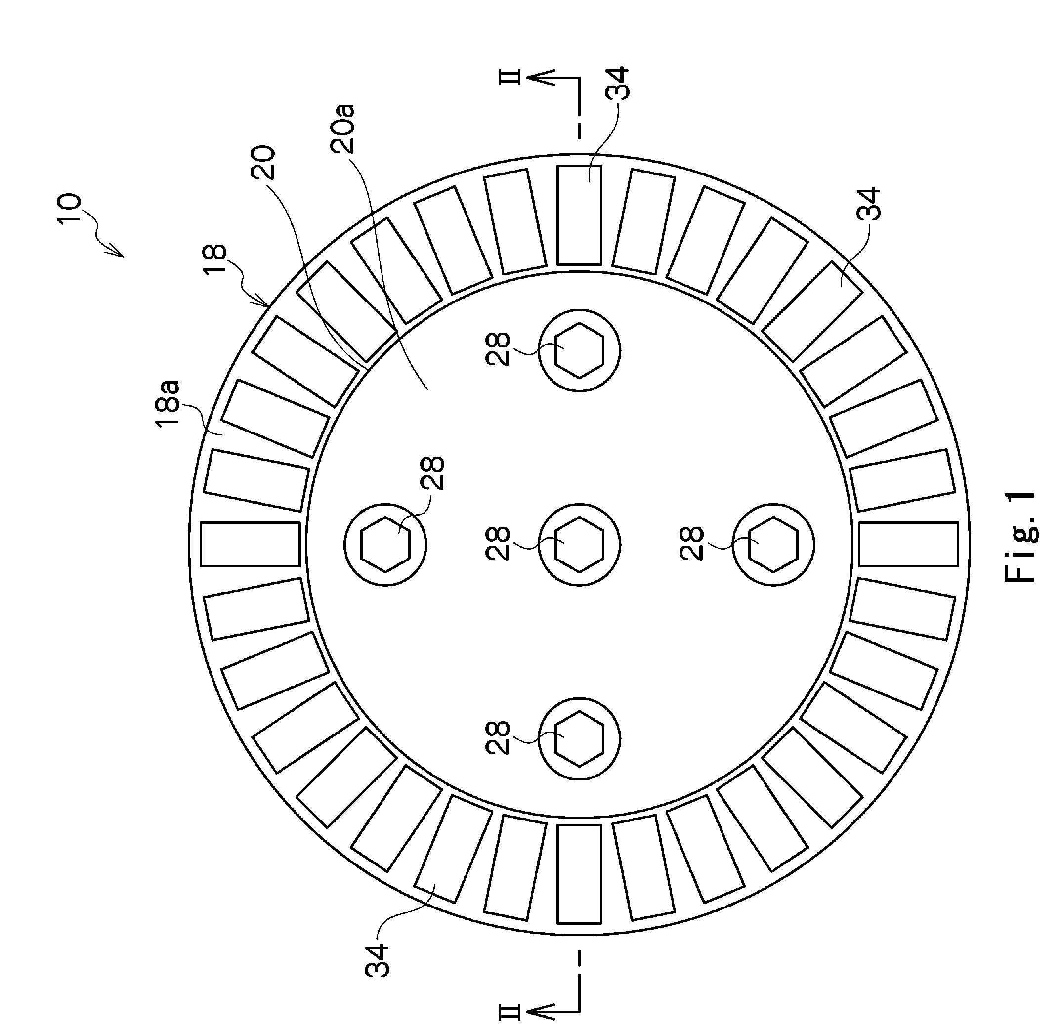
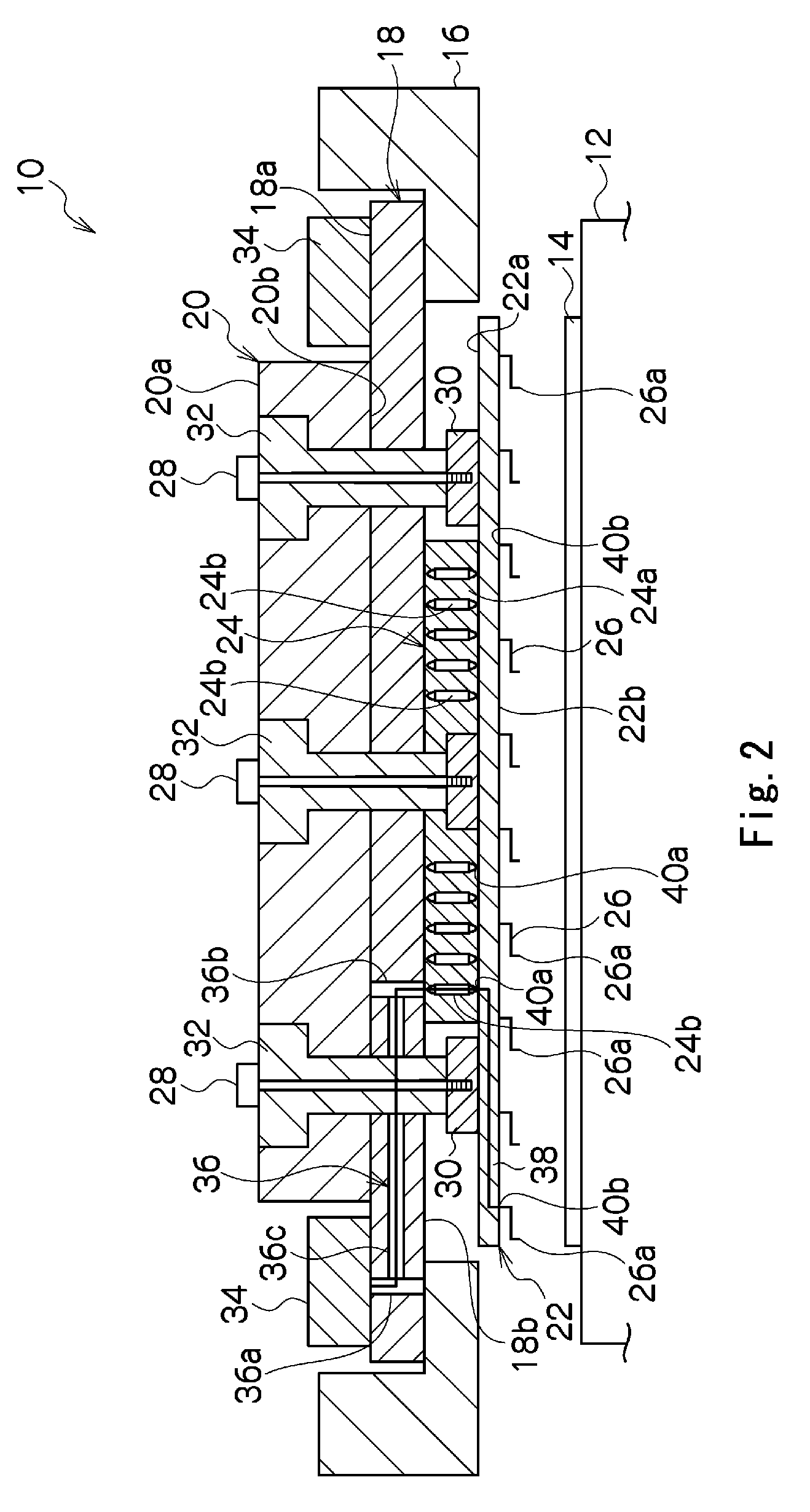
[0027]The electrical connecting apparatus 10 according to the present invention is shown in FIGS. 1 and 2. This electrical connecting apparatus 10 is, as shown in FIG. 2, used, for example, for an electrical inspection of a semiconductor wafer 14 on a known vacuum chuck 12 which constitutes a sample table of a tester. In the semiconductor wafer 14, a plurality of IC circuits are incorporated, and for an electrical inspection of those IC circuits, though not shown, are used for connecting each connection pad of each IC circuit to an electric circuit of a tester body (not shown).

[0028]The electrical connecting apparatus 10 is used, attached to a tester head of the tester, for example. The electric connecting apparatus 10 comprises, as shown in FIG. 2: a circular plate-like circuit board 18 held at its edge portion on an annular card holder 16 provided in the tester head; a circular plate-like reinforcing plate 20 mounted on the upside 18a of the circuit board and having a smaller diam...


PUM


Abstract

A wiring path of a circuit board has a first vertical path portion penetrating the circuit board at its outer edge in its thickness direction and connected to a connector on one surface, a second vertical path portion penetrating the circuit board in its thickness direction and connected to the electric coupler on the other surface, and a lateral path portion connecting both vertical portions, and the second vertical path portion is formed within an arrangement area (S1) of a reinforcing plate. One connecting end portion (electric coupler side) of the wiring path of the circuit board is disposed within the arrangement area (S1) of the reinforcing plate. On the other hand, the other connecting end portion (probe side) of the wiring path of the circuit board is disposed to be dispersed in an arrangement area (S2) wider than the arrangement area (S1) of the reinforcing plate.

Description

TECHNICAL FIELD[0001]The present invention relates to an electrical connecting apparatus such as a probe card for use in electrical connection between a device under test, e.g., an integrated circuit and a tester for conducting its electrical inspection to electrically test an electric circuit.BACKGROUND[0002]A conventional electrical connecting apparatus of this type comprises, for example, a printed circuit board (PCB) which is provided inside with a plurality of wiring paths, and on one surface of which a circuit board having a reinforcing plate attached and a probe board is mounted, the probe board being provided with a plurality of probes on the opposite face of the surface opposing the circuit board. Between both the boards, an electric coupler such as a pogo pin connector connecting each of the wiring path of the circuit board and each wiring path of the probe board corresponding to the wiring path are disposed, the circuit board, the electric coupler and the probe board bein...

Claims


Application Information

Patent Timeline
Patent Type & Authority Applications(United States)
IPC IPC(8): G01R1/04
CPCG01R31/2889G01R1/07378G01R1/067H01L22/00
Inventor MIYAGI, YUJIMIURA, KIYOTOSHIKIYOFUJI, HIDEHIROAKAHIRA, AKIHISAINOUE, TATSUO
Owner NIHON MICRONICS
Why Eureka
Try Eureka