
Heat pipe supplemented transformer cooling

a heat pipe and transformer technology, applied in the direction of electrical equipment, basic electric elements, lighting and heating equipment, etc., can solve the problems of resistive heating, transformer heating, heat dissipation from the conductor, etc., and achieve the effect of enhancing the cooling of the transformer

Inactive Publication Date: 2008-05-29
HONEYWELL INT INC
View PDF17 Cites 25 Cited by
  • Summary
  • Abstract
  • Description
  • Claims
  • Application Information

AI Technical Summary

Benefits of technology

[0007]The present invention is directed to a method for cooling a transformer and to transformer apparatuses. According to a first aspect of the present invention, a transformer apparatus comprises: a conduction cooled electrical transformer mounted to a cold plate; and a heat pipe for supplementing cooling of the transformer, the heat pipe comprising a first end, a second end, and a sealed low pressure cavity containing an amount of a fluid, wherein the first end of the heat pipe is located in a hot region of the transformer, the second end is maintained colder than the first end by contact with the cold plate, and heat produced at the first end by operation of the transformer is moved to the second end by a closed loop vapor cycle in the sealed low pressure cavity using the fluid of the heat pipe.
[0008]According to a second aspect of the present invention, a transformer apparatus comprises: an electrical transformer mounted to a cold plate; and a heat pipe for supplementing cooling of the transformer, the heat pipe comprising a first end, a second end, and a sealed low pressure cavity containing an amount of a fluid, wherein the first end of the heat pipe is immovably embedded in a hot region of the transformer, the second end is maintained colder than the first end by contact with the cold plate, and heat produced at the first end by operation of the transformer is moved to the second end by a closed loop vapor cycle in the sealed low pressure cavity using the fluid of the heat pipe.
[0009]According to a third aspect of the present invention, a method for cooling a transformer comprises: cooling the transformer by conduction; and enhancing cooling of the transformer using a heat pipe, the enhancing step including placing a first end of the heat pipe in a hotspot region of the transformer, maintaining a second end of the heat pipe colder than the first end, and moving heat from the first end to the second end by vaporizing a fluid in a sealed low pressure cavity of the heat pipe, transporting the vaporized fluid to the second end, condensing the vaporized fluid, and returning the condensed fluid to the first end by a capillary action along a wall of the heat pipe.

Problems solved by technology

For example, current flowing through the transformer windings causes resistive heating of the transformer conductors, and consequently, heat dissipates from the conductors.
Induced eddy currents may circulate within the core of the transformer, causing resistive heating.
Residual DC currents in the transformer also lead to transformer heating.

Method used


Image

  • Heat pipe supplemented transformer cooling
  • Heat pipe supplemented transformer cooling
  • Heat pipe supplemented transformer cooling

Examples


Embodiment Construction

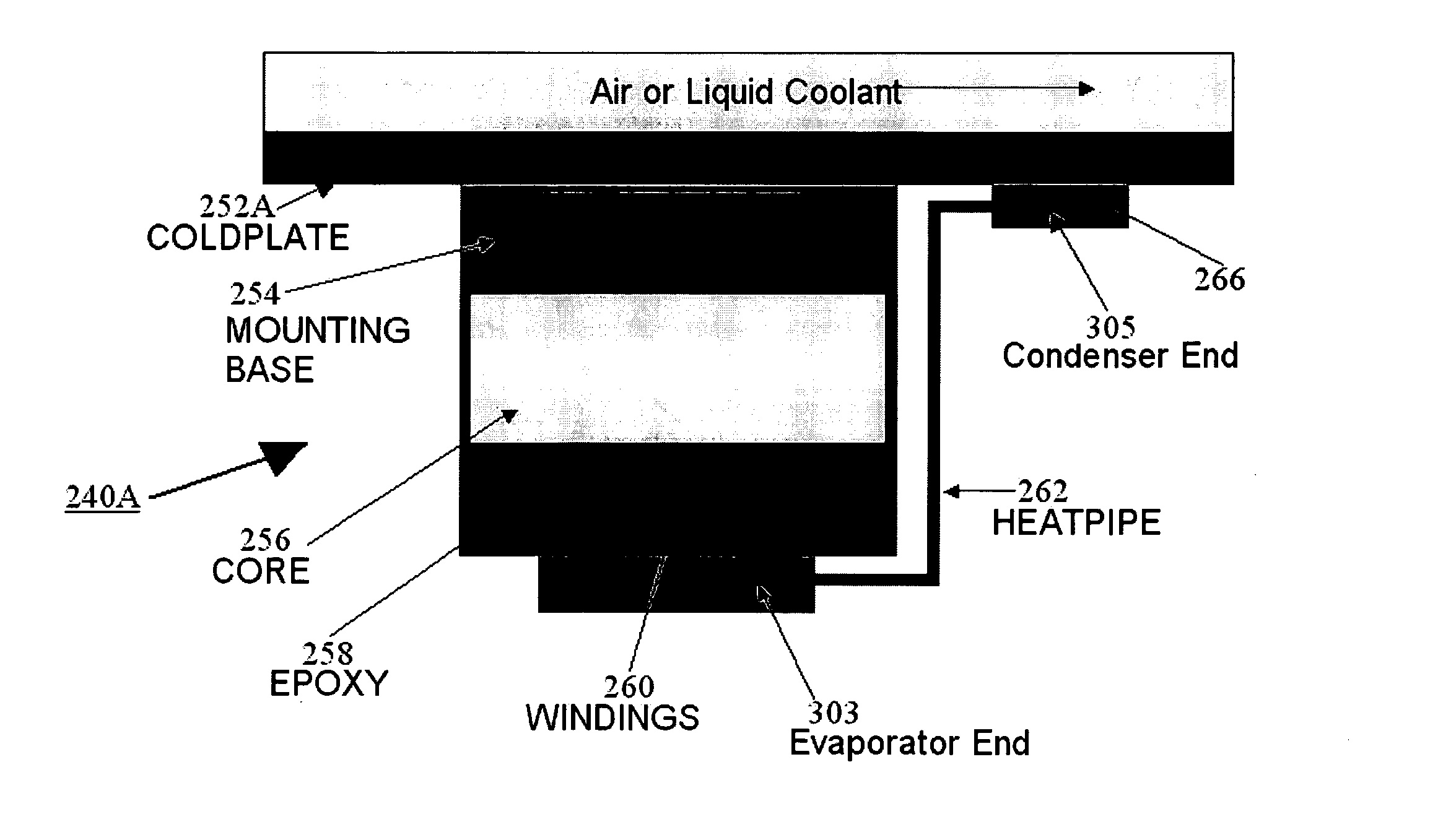
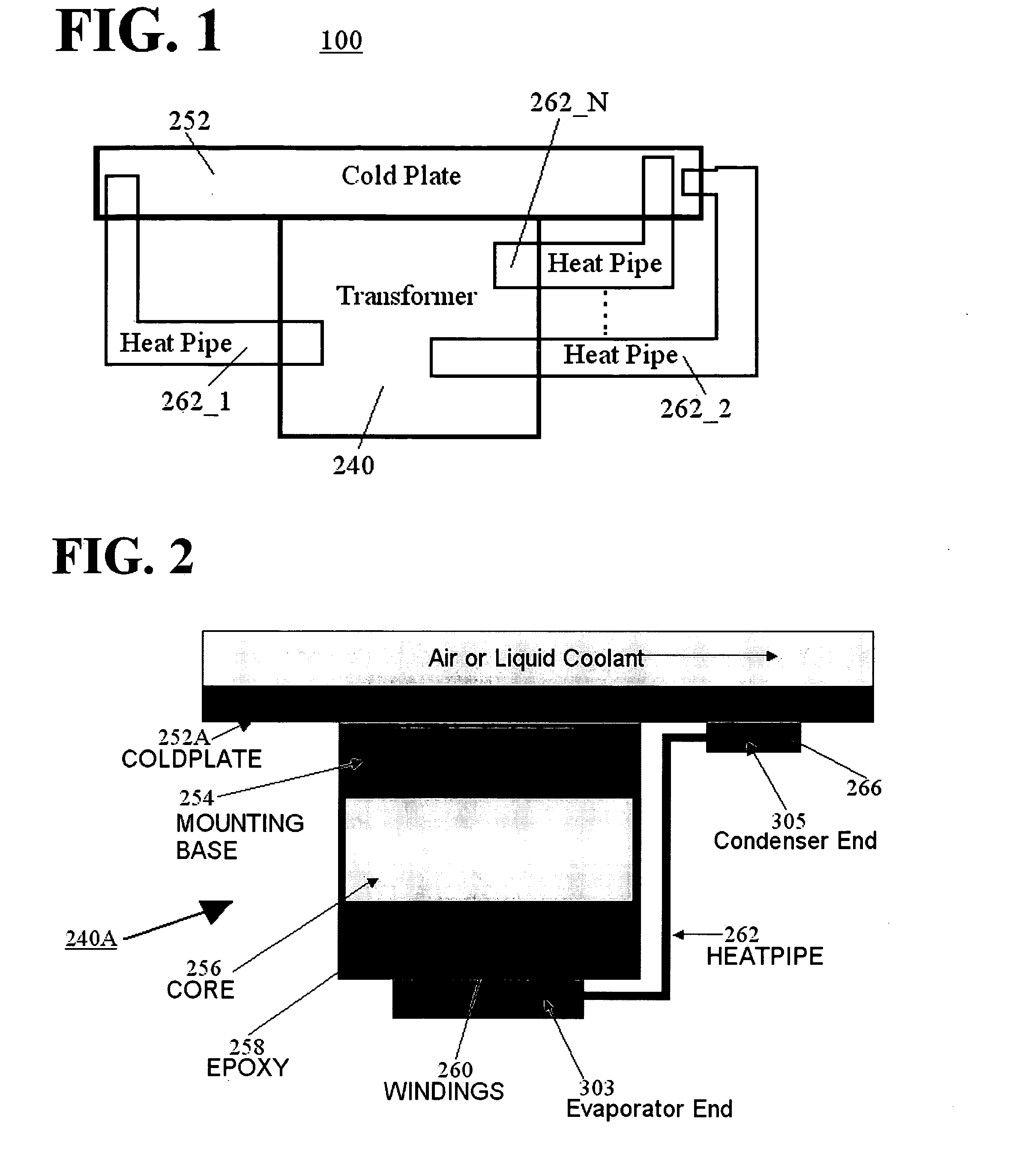
[0017]Aspects of the invention are more specifically set forth in the accompanying description with reference to the appended figures. FIG. 1 is a general block diagram of a system containing a transformer with heat pipe supplemented cooling according to an embodiment of the present invention. The system 100 illustrated in FIG. 1 includes the following components: a cold plate 252; a transformer 240; and heat pipes 262_1, 262_2, . . . , 262_N. Operation of the system 100 in FIG. 1 will become apparent from the following discussion.

[0018]System 100 may be associated with an aircraft, a ship, a laboratory facility, an industrial environment, a residential environment, etc. The cold plate 252 is at a lower temperature than the transformer 240. The cold plate 252 may be any type of system maintained at a lower temperature. The cold plate 252 may be, for example, part of a refrigerant system, air cooled system, water cooled system, etc.

[0019]Transformer 240 heats up during its operation....


PUM

PropertyMeasurementUnit
pressureaaaaaaaaaa
thermal resistanceaaaaaaaaaa
areaaaaaaaaaaa

Abstract

A method for cooling a transformer and transformer apparatuses are implemented. A transformer apparatus, according to one embodiment, comprises: a conduction cooled electrical transformer (240) mounted to a cold plate (252); and a heat pipe (262) for supplementing cooling of the transformer (240), the heat pipe (262) comprising a first end (303), a second end (305), and a sealed low pressure cavity containing an amount of a fluid (311), wherein the first end (303) of the heat pipe (262) is located in a hot region of the transformer (240), the second end (305) is maintained colder than the first end (303) by contact with the cold plate (252), and heat produced at the first end (303) by operation of the transformer (240) is moved to the second end (305) by a closed loop vapor cycle in the sealed low pressure cavity using the fluid (311) of the heat pipe (262).

Description

BACKGROUND OF THE INVENTION[0001]1. Field of the Invention[0002]The present invention relates to a cooling method and apparatus, and more particularly, to a cooling method and apparatus for a transformer, using a heat pipe.[0003]2. Description of the Related Art[0004]Electrical transformers are ubiquitous devices used for energy transfer and conversion. During operation, transformers heat up due to a plurality of factors. For example, current flowing through the transformer windings causes resistive heating of the transformer conductors, and consequently, heat dissipates from the conductors. Induced eddy currents may circulate within the core of the transformer, causing resistive heating. The heat produced by eddy currents in the core radiates out to other components of the transformer. Residual DC currents in the transformer also lead to transformer heating. Hence, transformer heating accompanies transformer operation. The amount of heat dissipated during transformer operation depe...

Claims


Application Information

Patent Timeline
Patent Type & Authority Applications(United States)
IPC IPC(8): H01F27/18H01F27/08H01F27/10
CPCF28D15/0266F28D15/0275F28F3/12H01F27/18H01F27/22F28F2013/006
Inventor TEGART, DON A.
Owner HONEYWELL INT INC
Learn More