Method and system for live video production over a packeted network

a live video and packeted network technology, applied in the field of live video production systems, can solve the problems of limiting the number of video signals, waste of video cables which are not being used by the video stream, and static number of video cables in these conventional video production systems, so as to achieve the effect of easy expansion of switchers and reducing the number of cables

Inactive Publication Date: 2008-05-29
DIEDERICHSEN FLORIAN
View PDF12 Cites 38 Cited by
  • Summary
  • Abstract
  • Description
  • Claims
  • Application Information

AI Technical Summary

Benefits of technology

[0030]An exemplary embodiment of the present invention has many advantages, such as, for example, the use of standard cabling, a scalable architecture, which provides for easily expandable switchers, video monitors available at every network patch, only the needed bandwidth is cabled, there is no need for distribution amplifiers and one cable per signal, the format is independent, big and expensive rout

Problems solved by technology

However, video signals in these conventional video production systems are still transferred over lines that are individually dedicated to each signal to specialized machinery, which manipulates or routes the video.
Since many video production systems are required to simultaneously process a large number of video signals, a large number of video cables are required to handle all of these video signals.
Further, the number of video cables in these conventional video production systems remains static, even though the number of video signals that are actually being processed by theses systems change.
When these video systems handle a small number of video streams, then the video cables which are not being used by the video streams are wasted.
On the other hand, the number of video cables also limits the number of video signals, which are capable of being processed by the system.
These systems are not capable of processing more video signals, than the number of video

Method used


Image

  • Method and system for live video production over a packeted network
  • Method and system for live video production over a packeted network
  • Method and system for live video production over a packeted network

Examples


Embodiment Construction

[0053]Referring now to the drawings, and more particularly to FIGS. 1-7, there are shown exemplary embodiments of the method and structures of the present invention.

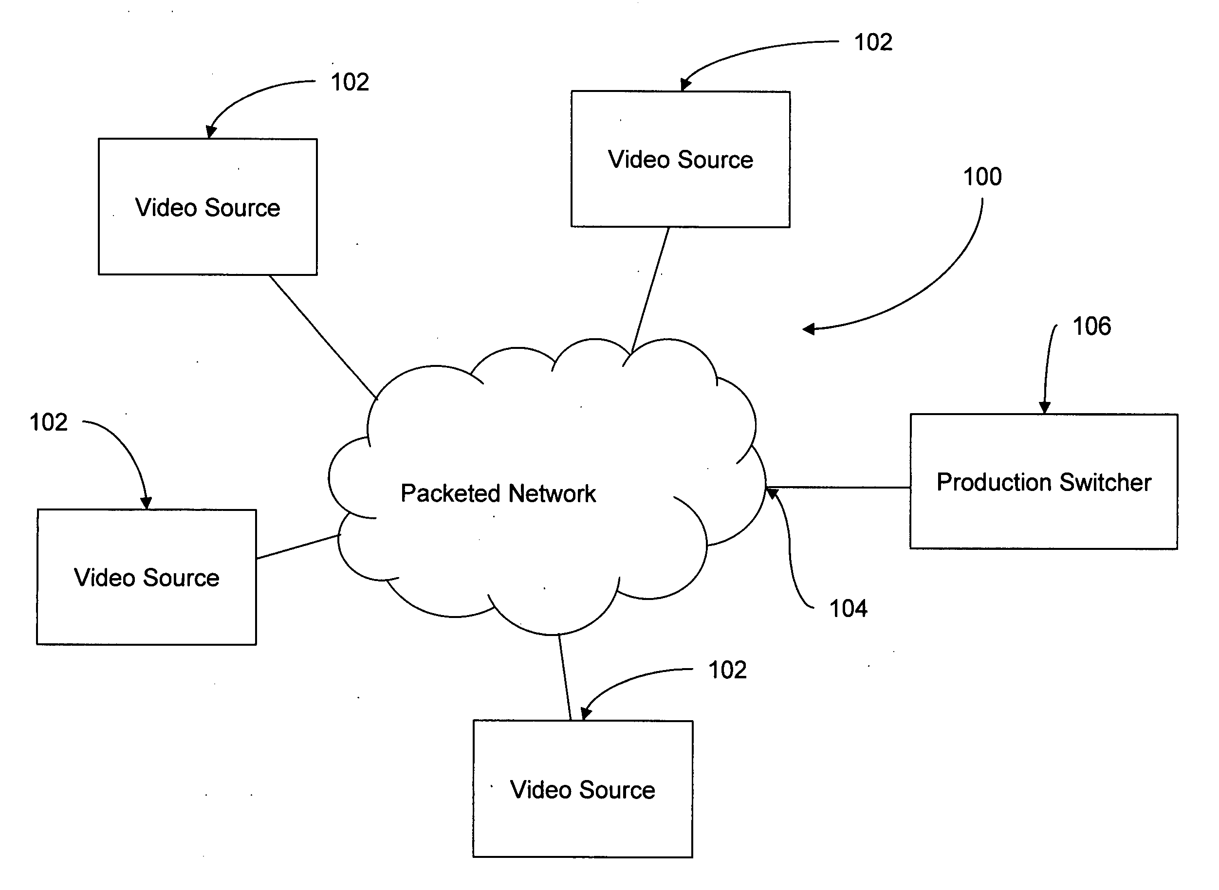
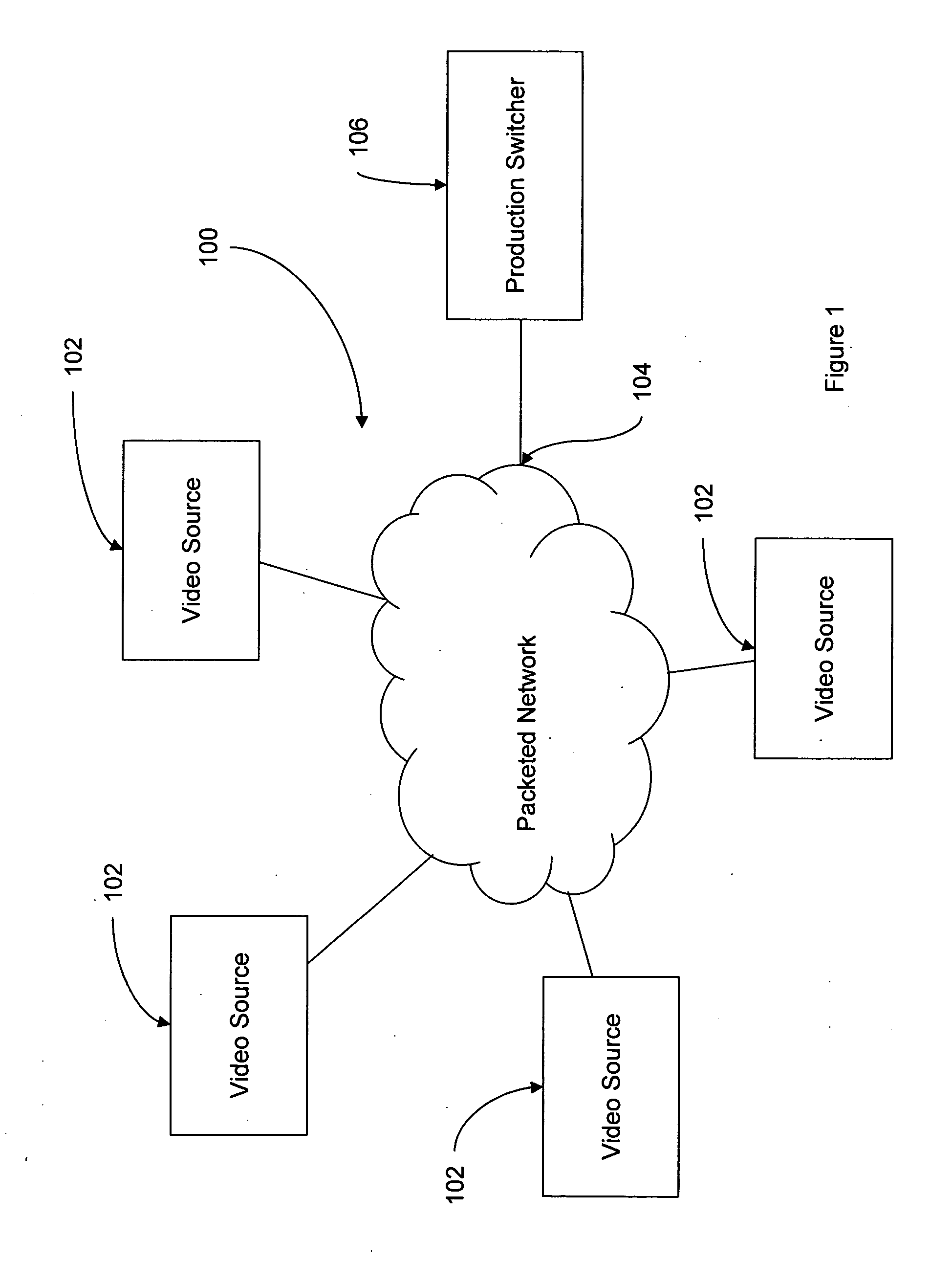
[0054]FIG. 1 illustrates one exemplary embodiment of a system 100 for live video production over a packeted network in accordance with the present invention. The system 100 includes video sources 102 and a production switcher 106 in communication with a packeted network 104. The packeted network 104 may be any packeted network such as, for example a variable-latency, packeted-network, a wide-area network, a local area network, the Internet, or the like.

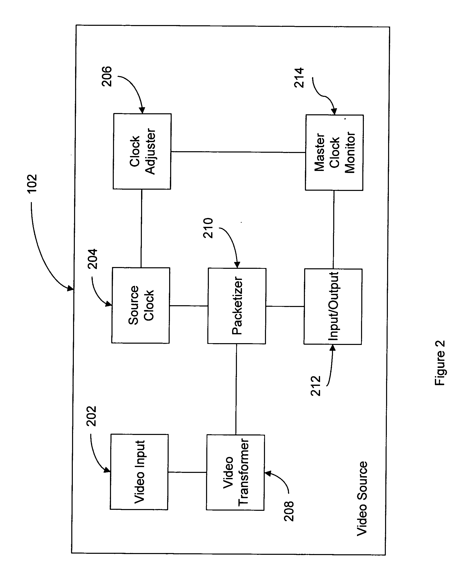
[0055]FIG. 2 illustrates an exemplary video source 200 in accordance with the system of FIG. 1. The video source 200 includes a video input 202, a source clock 204, a clock adjuster 206, a video transformer 208, a packetizer 210, an input / output interface 212, and a master clock monitor 214. The video input 202 receives a video signal such as, for example a serial digital ...


PUM


Abstract

A method (and system) for live video production upon video signals transported over a packeted network, includes a master clock providing a packeted time code signal to the packeted network, and a video source having a source clock that is synchronized to the master clock based upon the packeted time code signal from the master clock.

Description

BACKGROUND OF THE INVENTION[0001]1. Field of the Invention[0002]The present invention generally relates to live video production systems. More particularly, the present invention relates to a method and system for performing live video production upon video signals transmitted over a packeted network.[0003]2. Description of the Related Art[0004]Conventional video production facilities, such as, for example, a television studio, a cable broadcast facility, a commercial production facility, or a linear video editing bay, amongst other specialized video equipment, all rely upon, for example, the use of a video production switcher (also called a “video switcher”, “video mixer” or a “vision mixer”). A video production switcher is conventionally used in state of the art video production systems. These conventional vision mixer systems include a control panel that includes various user interfaces, such as, for example, buttons, transition (or “T-bars”), rotary knobs, and the like. The cont...

Claims


Application Information

Patent Timeline
IPC IPC(8): H04N5/268
CPCH04N21/2343H04N21/6125H04N21/2665H04N21/242
Inventor DIEDERICHSEN, FLORIAN
Owner DIEDERICHSEN FLORIAN
Why Eureka
Try Eureka