Multi-layered multifocal lens with blended refractive index

a multi-layered, multifocal technology, applied in spectacles/goggles, instruments, spectacles/goggles, etc., can solve the problems of poor vision, restricted useful area of progressive and near vision zones of lenses, and low popularity of multifocal lenses. achieve the effect of improving optical attributes

Inactive Publication Date: 2008-05-29
VOLK DONALD A
View PDF23 Cites 47 Cited by
  • Summary
  • Abstract
  • Description
  • Claims
  • Application Information

AI Technical Summary

Benefits of technology

[0013]Based on the foregoing, there is found to be a need to provide a multifocal spectacle lens that avoids the problems associated with the prior art lenses and which in particular has improved optical attributes. The benefits are derived from a multi-layered lens incorporating a refractive index change that provides the required powers for different distance viewing portions. It is therefore a main object of the present invention to provide a multi-layered multifocal lens that comprises at least one layer incorporating portions of different refractive index that interface along a refractive index blend that will provide clear unrestricted vision through the various portions of the lens.

Problems solved by technology

Blended bifocal lenses have not gained great popularity as the blend area incorporates a curvature inflection or deformation that exhibits blur and distortion.
Progressive lenses have cosmetic appeal as the segment line and visibility present in bifocal and trifocal lenses is absent, but the useful area of the progressive and near vision zones of the lens is restricted as aberrations resulting from the power change of the lens result in poor vision especially in the lower lateral portions of the lens.
As a result, some individuals do not adjust well to progressive lenses and prefer either reading glasses or bifocal or trifocal spectacle lenses.
None of the lens systems has ever found commercial success, due in part to the difficulty involved in their respective manufacturing processes and the relatively small amount of refractive index change induced.
Furthermore, if a prescription incorporating cylinder power is produced on either the front or back surface, the cylinder power will vary and cause aberrations as a result of the gradually or progressively varying refractive index.
The variable index coating that comprises the inner layer of this lens does not provide the progressive add power of the lens, rather as stated in the patent it corrects for aberrations of the patient's eye.
The lens has many of the limitations typical of aspheric progressive lenses.
Although it may be desirable to be able to spray in thick sections this will not always be possible as the density of one resin or monomer may be greater than the other, resulting in one sliding under the other by the pull of gravity.

Method used


Image

  • Multi-layered multifocal lens with blended refractive index
  • Multi-layered multifocal lens with blended refractive index
  • Multi-layered multifocal lens with blended refractive index

Examples


first embodiment

[0097]FIG. 5 is a table listing the CREN values of a complement of lenses of the first embodiment according to the RID of the changing refractive index layer(s) and add power of the lens. The refractive index values for all calculations are those listed above with reference to FIG. 4. Add powers in the table range from 1 to 3.5 diopters. The CREN numbers for the example lenses above, having all parameters the same except for lens form, range from 18.436 to 18.729, and define the major portion of the 18.07-19.10 range listed in the category at the intersection of the 0.24 RID and the 2.5 diopter add. The category range on the chart has been widened by 2% beyond the numerical range of the example lenses to 18.07-19.10 to include additional lens forms not included in FIG. 4. The other category ranges in FIG. 5 likewise have been widened by 2%. The 18.07-19.10 CREN range represents a very usable but just medium efficiency group of changing refractive index lenses of the present inventio...

third embodiment

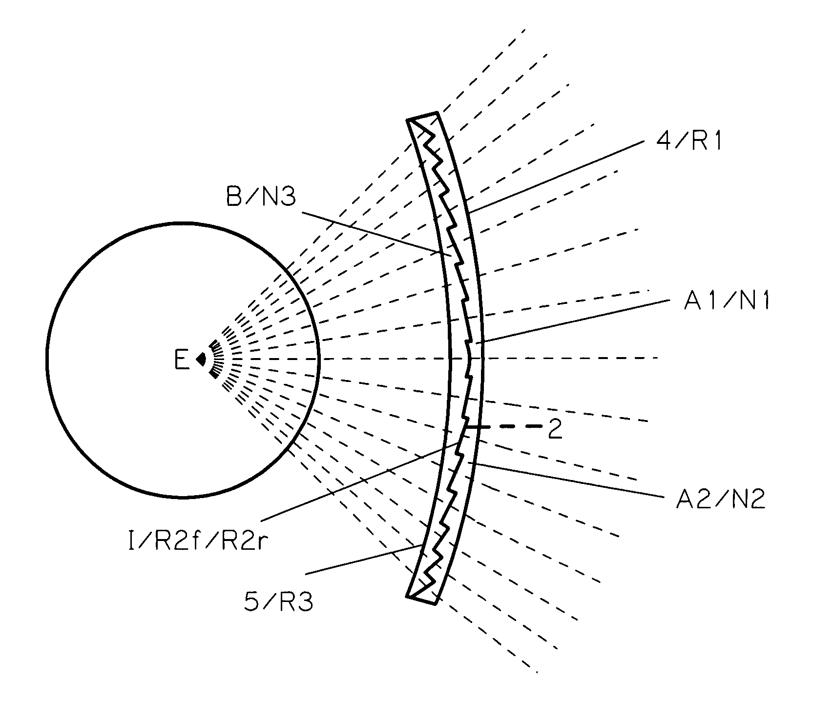
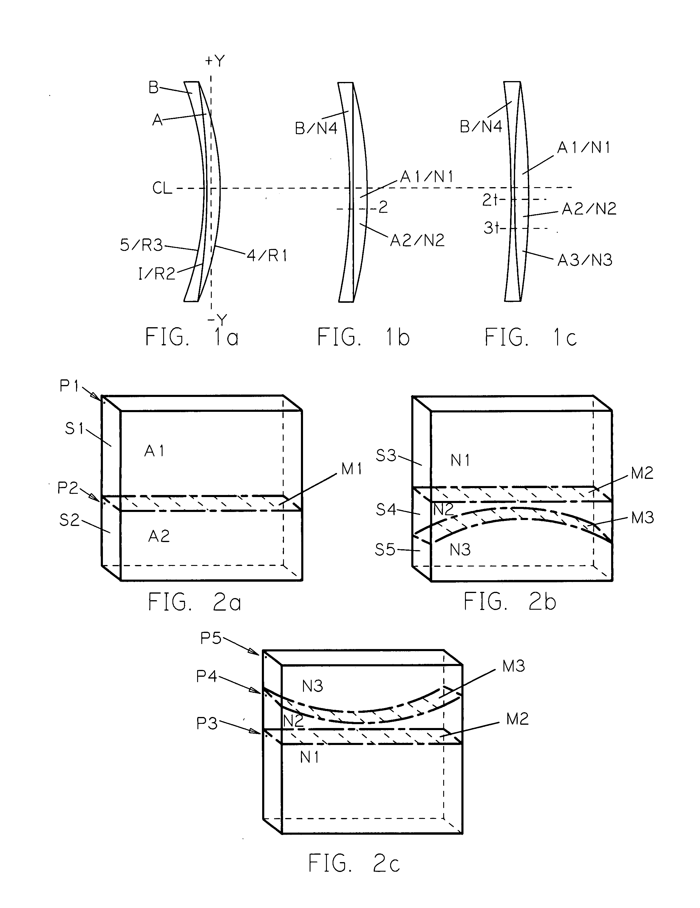
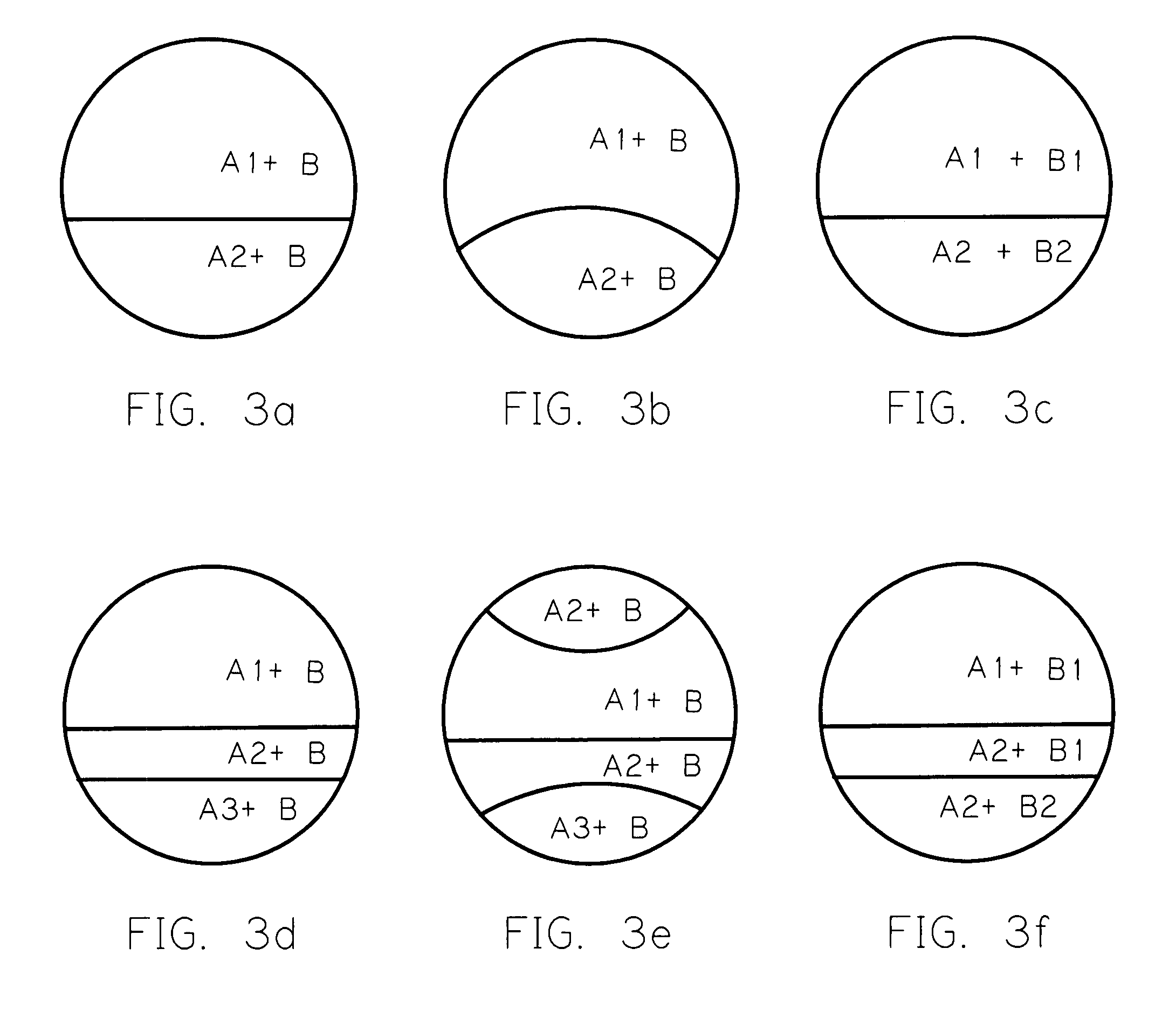
[0110]Referring to FIG. 9 there is shown a doublet lens configuration of the invention. Anterior lens section A comprises a generally constant refractive index layer, a right at the I are I in and lens section B comprises the changing refractive index layer of the lens. Section A has minus power and section B has plus power. In the two examples provided the internal interface curvature R2 is concave with respect to section A. In this embodiment the refractive index of the near vision portion is greater than that of the distance vision portion, therefore providing add power for near vision.

[0111]Using similar conventions for identifying and defining the lens as shown in the previously illustrated embodiments and examples, lens layer B is comprised of an optically transparent material having two portions with different refractive index values. B1 corresponds to the distance vision portion of the lens and has a refractive index value N1. B2 corresponds to the near vision portion of the...

fourth embodiment

[0113]Referring to FIGS. 10a, 10b and 10c there are shown three doublet lens configurations of the invention. Collectively, anterior lens section A comprises a generally constant refractive index section of the lens and section B comprises the changing refractive index section of the lens. Section A has plus power and section B has minus power. Anterior surface 4 of lens layer A has a curvature with a radius value R1, internal interface I has a curvature R2, and posterior surface 5 of lens section B has a curvature with a radius value R3. In this embodiment the refractive index of the distance vision portion is greater than that of the near vision portion, therefore providing add power for near vision.

[0114]Separately, FIG. 10a shows the embodiment wherein the internal interface curvature R2 is concave with respect to lens section A, FIG. 10b shows the embodiment wherein the internal interface curvature is piano, and FIG. 10c shows the embodiment wherein the internal interface curva...


PUM

PropertyMeasurementUnit
sizesaaaaaaaaaa
sizesaaaaaaaaaa
refractive indicesaaaaaaaaaa

Abstract

The lens of the present invention relates to multifocal spectacle lenses, including bifocal and trifocal lenses, with improved cosmetic appearance, optical performance and wide visual field. The lens comprises a plurality of axially layered and bonded lens sections of continuous curvature at least one of which has a changing refractive index incorporating a refractive index blend area oriented transverse to a meridian of the lens. The blend eliminates visibility of the joining area of adjacent portions of generally constant refractive index and the abrupt magnification shift and image jump typical of segmented multifocal lenses. The areas of generally constant refractive index provide the refractive powers for corresponding discrete vision portions of the lens. The other layer(s) of the lens incorporates a constant or similarly changing refractive index.

Description

[0001]This application claims the benefit of U.S. Provisional application 60 / 854,467 filed Oct. 24, 2006.FIELD OF THE INVENTION[0002]The lens of the present invention relates to multifocal spectacle lenses, including bifocal and trifocal lenses, with improved cosmetic appearance, optical performance and wide visual field. The lens comprises a plurality of axially layered and bonded lens sections of continuous curvature at least one of which has a changing refractive index incorporating a refractive index blend area oriented transverse to a meridian of the lens. The blend eliminates visibility of the joining area of adjacent portions of generally constant refractive index and the abrupt magnification shift and image jump typical of segmented multifocal lenses. The areas of generally constant refractive index provide the refractive powers for corresponding discrete vision portions of the lens. The other layer(s) of the lens incorporates a constant or similarly changing refractive inde...

Claims


Application Information

Patent Timeline
Patent Type & Authority Applications(United States)
IPC IPC(8): G02C7/06B29D11/00
CPCB29D11/00028B29D11/00355G02C2202/16G02C7/061G02C2202/12G02C7/06
Inventor VOLK, DONALD A.
Owner VOLK DONALD A
Why Eureka
Try Eureka