Tunneling magnetic sensor including tio-based insulating barrier layer and method for producing the same

a magnetic sensor and insulating barrier technology, applied in the field of magnetic sensors, can solve the problems of undesirable magnesium concentration in the above range of the insulating barrier layer, and achieve the effect of increasing the resistance change rate (r/r)

Inactive Publication Date: 2008-05-29
ALPS ALPINE CO LTD
View PDF10 Cites 6 Cited by
  • Summary
  • Abstract
  • Description
  • Claims
  • Application Information

AI Technical Summary

Benefits of technology

[0020]Preferably, the MgO layer is disposed on one or both of the top and bottom surfaces of the TiO layer to more successfully increase the rate of resistance change (ΔR / R). MgO is more capable of increasing the rate of resistance change (ΔR / R) than TiO. Accordingly, the rate of resistance change (ΔR / R) can be successfully increased by forming the MgO layer at one or both of the interfaces between the insulating barrier layer and the first magnetic layer and between the insulating barrier layer and the second magnetic layer.
[0022]In the present invention, the insulating barrier layer may have a region where the concentration of magnesium varies in a thickness direction. The concentration of magnesium tends to be varied during, for example, annealing in the production of the tunneling magnetic sensor. Preferably, the concentration of magnesium is higher near one or both of the top and bottom surfaces of the insulating barrier layer than in the other region. This contributes to an increase in the rate of resistance change (ΔR / R).
[0025]The above process allows formation of a TiMgO insulating barrier layer containing magnesium in an amount of about 4 to about 20 atomic percent based on 100 atomic percent of the total content of titanium and magnesium. Accordingly, a tunneling magnetic sensor capable of providing a higher rate of resistance change (ΔR / R) at a lower RA than known tunneling magnetic sensors can be successfully and easily produced by the above process.
[0030]The tunneling magnetic sensor according to the present invention can provide a higher rate of resistance change (ΔR / R) at a lower RA than known tunneling magnetic sensors.

Problems solved by technology

An insulating barrier layer having a magnesium concentration exceeding the above range is undesirable because it tends to exhibit a lower rate of resistance change (ΔR / R) than a titanium oxide (TiO) insulating barrier layer.

Method used


Image

  • Tunneling magnetic sensor including tio-based insulating barrier layer and method for producing the same
  • Tunneling magnetic sensor including tio-based insulating barrier layer and method for producing the same
  • Tunneling magnetic sensor including tio-based insulating barrier layer and method for producing the same

Examples


examples

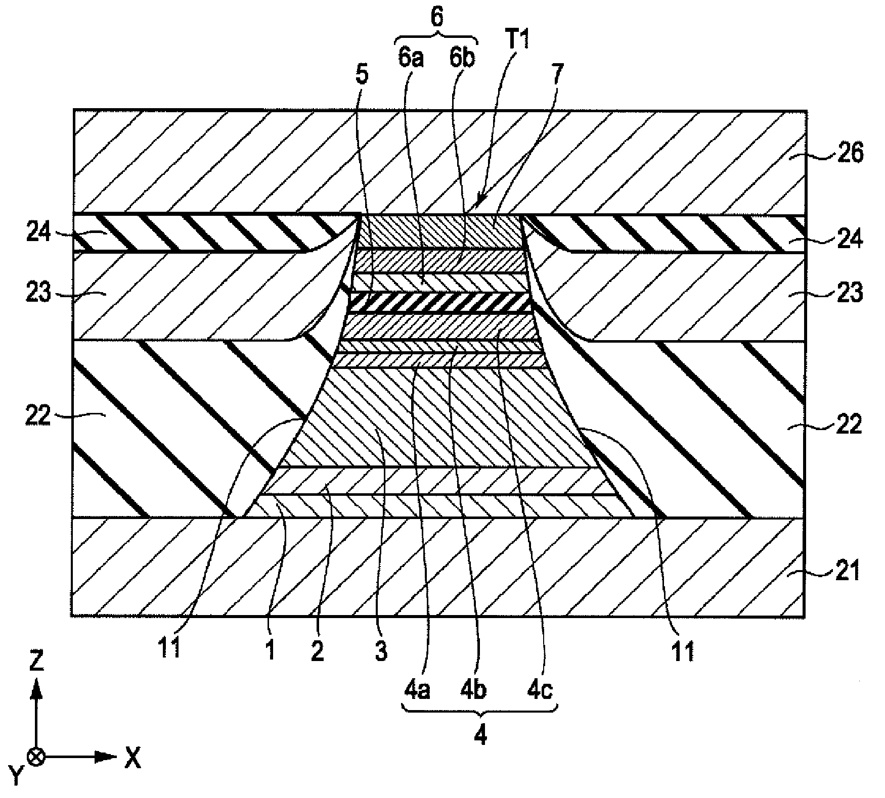
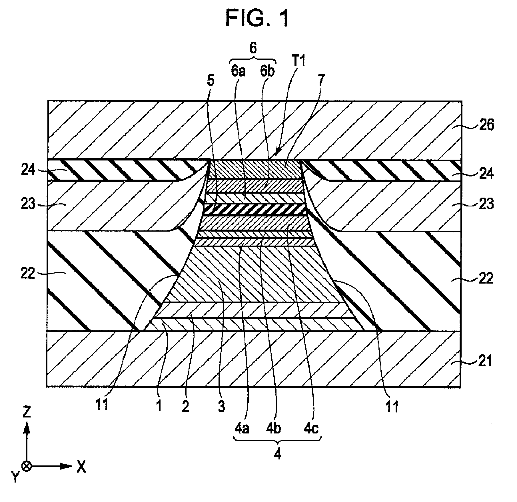
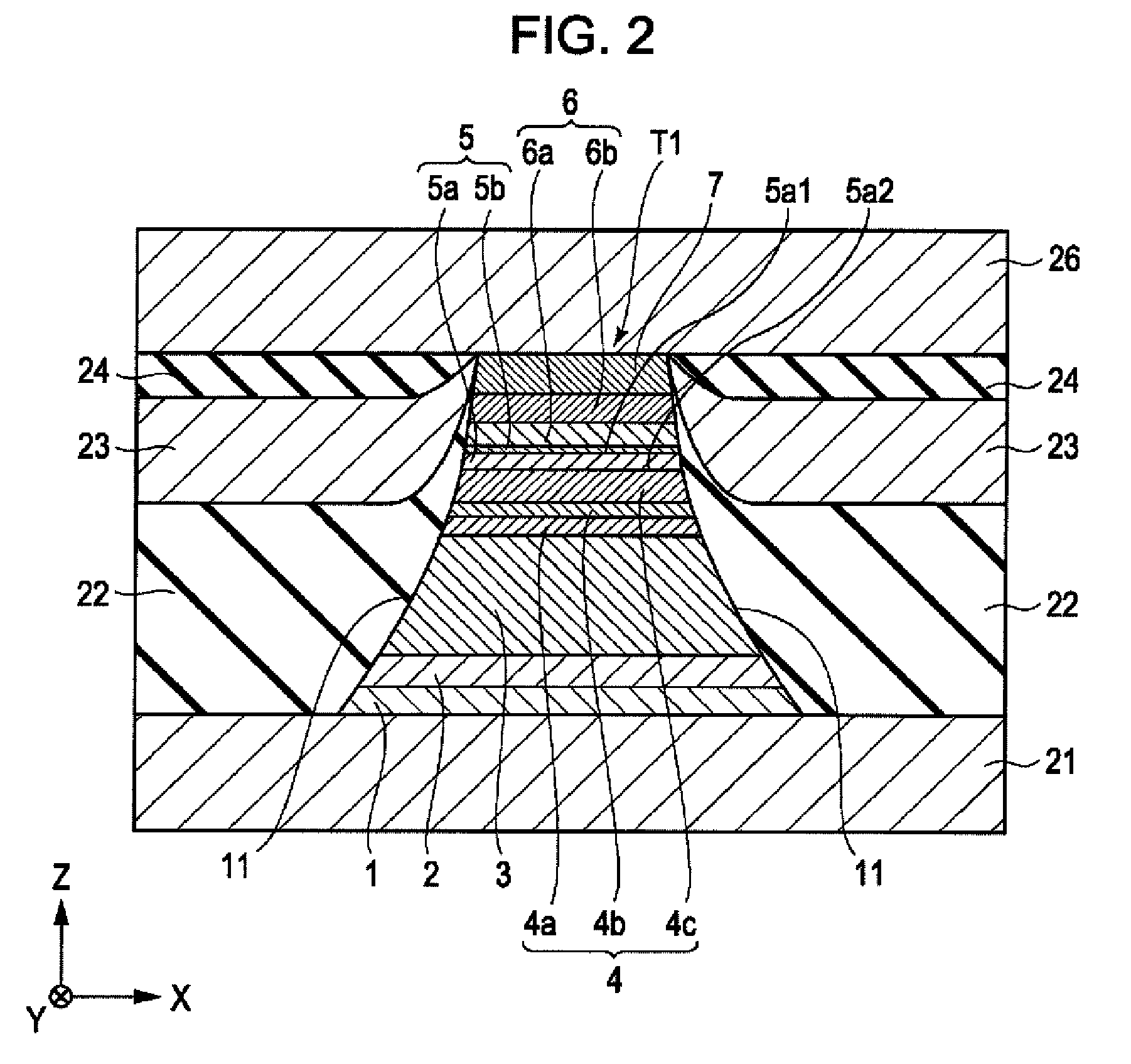
[0110]Tunneling magnetic sensors having the structure shown in FIG. 1 were produced.

[0111]The multilayer part T1 was formed by forming the base layer 1, the seed layer 2, the antiferromagnetic layer 3, the pinned magnetic layer 4, the insulating harrier layer 5, the free magnetic layer 6, a ruthenium layer having an average thickness of about 20 Å, and the protective layer 7 in the above order. The base layer 1 was formed of tantalum and had an average thickness of about 30 Å. The seed layer 2 was formed of NiFeCr and had an average thickness of about 50 Å. The antiferromagnetic layer 3 was formed of IrMn and had an average thickness of about 70 Å. The first pinned magnetic layer 4a was formed of Co70at%Fe30at% and had an average thickness of about 14 Å. The nonmagnetic intermediate layer 4b was formed of ruthenium and had an average thickness of about 9.1 Å. The second pinned magnetic layer 4c was formed of Co90at%Fe10ats and had an average thickness of about 18 Å. The enhancement ...


PUM

PropertyMeasurementUnit
concentrationsaaaaaaaaaa
magnetizationaaaaaaaaaa

Abstract

A tunneling magnetic sensor has a multilayer part including, from bottom to top, a pinned magnetic layer, an insulating barrier layer, and a free magnetic layer. The insulating barrier layer is formed of titanium magnesium oxide (TiMgO) and contains magnesium in an amount of about 4 to 20 atomic percent based on 100 atomic percent of the total content of titanium and magnesium. The insulating barrier layer thus does not have a high concentration of magnesium. This tunneling magnetic sensor can provide a higher rate of resistance change (ΔR / R) at a lower RA (the product of sensor resistance, R, and sensor area, A) than known tunneling magnetic sensors.

Description

CLAIM OF PRIORITY[0001]This application claims benefit of the Japanese Patent Application No. 2006-180619 filed on Jun. 30, 2006 and the Japanese Patent Application No. 2006-315961 filed on Nov. 22, 2006, which are hereby incorporated by reference.BACKGROUND OF THE INVENTION[0002]1. Field of the Invention[0003]The present invention relates to magnetic sensors utilizing a tunneling effect for use in magnetic sensing apparatuses, including magnetic playback apparatuses such as hard disk drives. In particular, the invention relates to a tunneling magnetic sensor capable of providing a high rate of resistance change (ΔR / R) at low RA (the product of sensor resistance, R, and sensor area, A) and a method for producing the tunneling magnetic sensor.[0004]2. Description of the Related Art[0005]A tunneling magnetic sensor, which utilizes a tunneling effect to cause a resistance change, includes a pinned magnetic layer, a free magnetic layer, and an insulating barrier layer (tunneling barrier...

Claims


Application Information

Patent Timeline
Patent Type & Authority Applications(United States)
IPC IPC(8): G11B5/33G11B5/127H04R31/00
CPCB82Y10/00Y10T29/49032B82Y40/00G01R33/093G01R33/098G11B5/3163G11B5/3906G11B5/3909G11B5/398H01F10/3254H01F10/3272H01F41/307H01L43/10H01L43/12H01F10/3295B82Y25/00H10N50/01H10N50/85
Inventor IDE, YOSUKEHASEGAWA, NAOYASAITO, MASAMICHIISHIZONE, MASAHIKONAKABAYASHI, RYONISHIMURA, KAZUMASA
Owner ALPS ALPINE CO LTD
Why Eureka
Try Eureka