
Hybrid clamshell blade system

a technology of clamshell blades and clamshells, which is applied in the direction of domestic cooling apparatus, cooling/ventilation/heating modification, lighting and heating apparatus, etc., can solve the problems of cost, complexity, weight, etc., and achieve the effect of high availability, power density, and electronics density

Inactive Publication Date: 2008-05-29
ISOTHERMAL SYST RES
View PDF13 Cites 101 Cited by
  • Summary
  • Abstract
  • Description
  • Claims
  • Application Information

AI Technical Summary

Benefits of technology

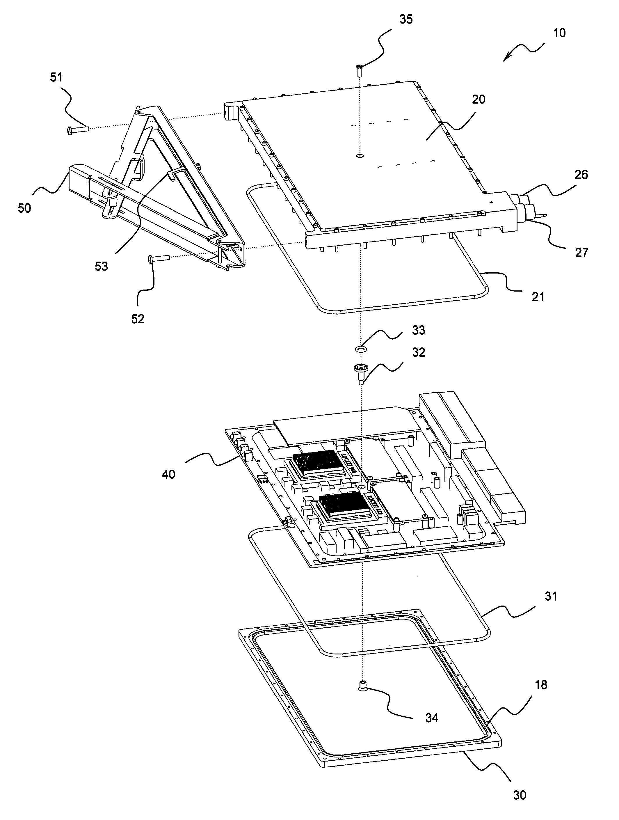
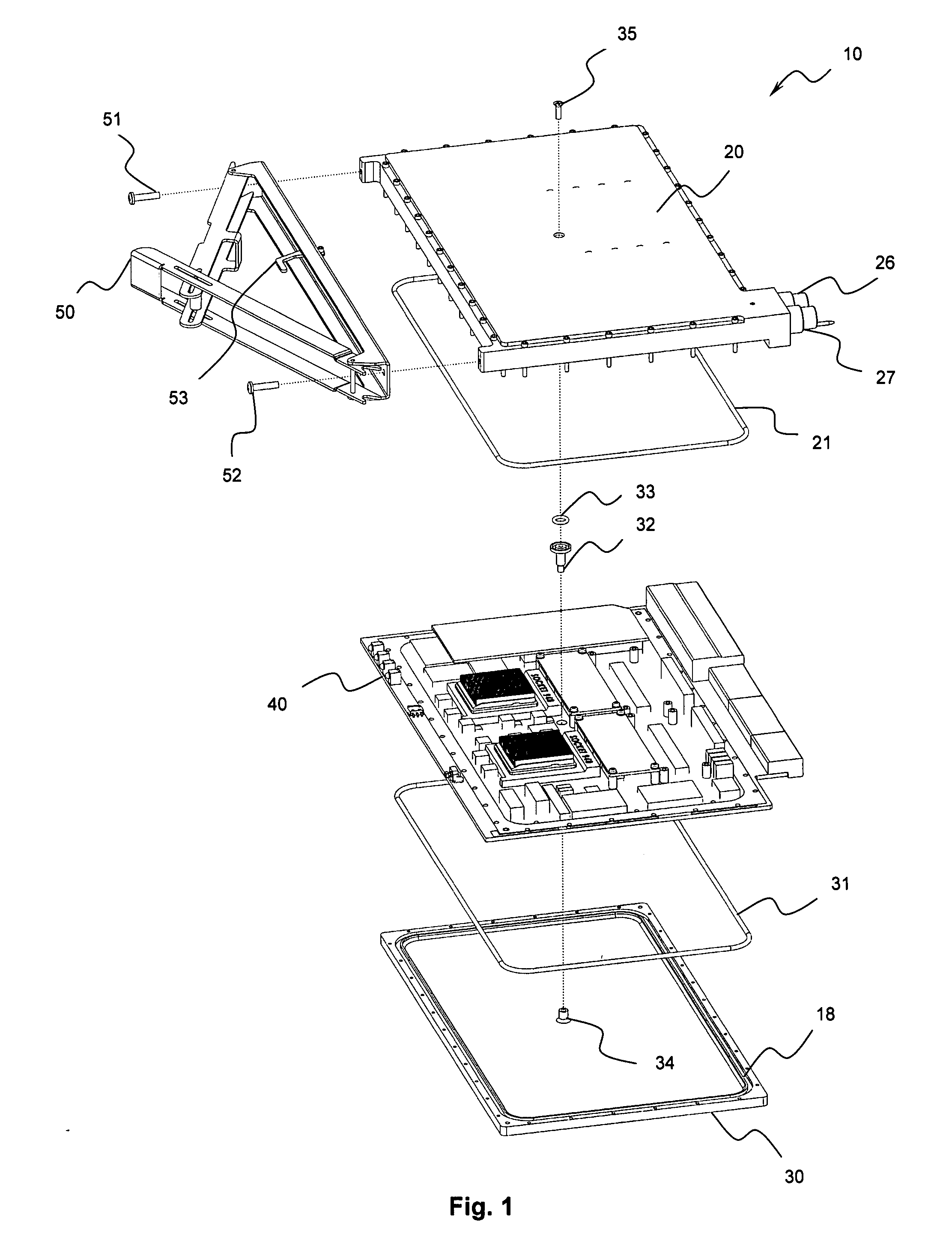
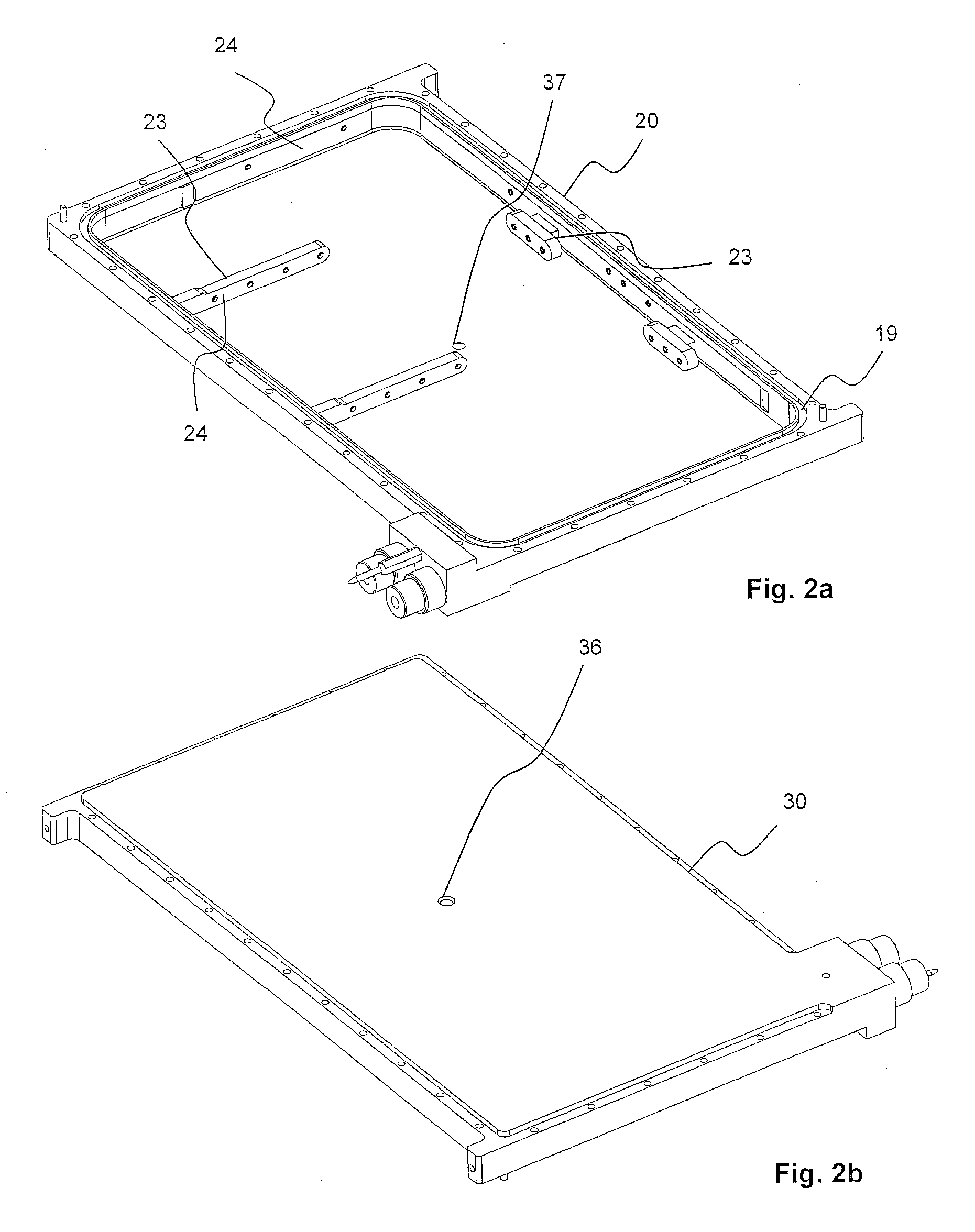
[0009]A liquid cooling system enclosed in a clamshell enclosure is thus provided for achieving maximum performance, power density, and electronics density inside a system that has characteristics of user-friendly serviceability, redundancy, and high availability. Further, in a data center environment, the hybrid clamshell system enables the user to capture over 80% of the heat and reject this to facility water. In a more extreme environment, the environmental isolation is of great importance. In addition, the hybrid clamshell system provides a full board cooling solution for high power density components, and creates a liquid-cooled building block that is form factor independent. In other words, the building block could be used on cPCI, ATX, VME, and mezzanine cards (AMC, PMC, etc.). This system is not limited to blade form factors, since other embodiments can be used.
[0011]With the addition of an inject / eject mechanism attached to the clamshell, the fully assembled blade can be “fluid hot-swapped” in and out of a system level chassis or subrack (common to cPCI or VME form factors, for example) with negligible loss of coolant (less than 0.05 mL). The fact that the coolant system remains closed during the removal and insertion of blades, provides an unprecedented level of serviceability.
[0012]Another key feature of the hybrid clamshell system is to provide a solution for deployment of dense stacked memory that otherwise cannot be air-cooled as well as deployment of air-cooled or spray cooled RTMs (rear transition modules) that enable the use of higher powered network (GigE, Infiniband) chips, graphics chips or other components that cannot be air-cooled. This system provides increased rack space due to the shallow chassis depth achievable.

Problems solved by technology

As air cooling heat sinks continue to be pushed to new performance levels, so has their cost, complexity, and weight.

Method used


Image

  • Hybrid clamshell blade system
  • Hybrid clamshell blade system
  • Hybrid clamshell blade system

Examples


Embodiment Construction

[0052]Many of the fastening, connection, manufacturing and other means and components utilized in this invention are widely known and used in the field of the invention described, and their exact nature or type is not necessary for an understanding and use of the invention by a person skilled in the art or science; therefore, they will not be discussed in significant detail. Furthermore, the various components shown or described herein for any specific application or embodiment of any element may already be widely known or used in the art or by persons skilled in the art or science; therefore, each will not be discussed in significant detail.

[0053]Turning now descriptively to the drawings, in which similar reference characters denote similar elements throughout the several views, FIGS. 1 through 25 illustrate a hybrid clamshell system. This specification will provide a thorough description of the embodiments described, however some features of the overall system likely have been omi...


PUM


Abstract

A hybrid clamshell system encapsulates two of the six sides of an electronic circuit board to provide a high heat density solution and environmental protection. The clamshell enclosures seal to both sides of the PCB and contain fluid shut-off couplings. A two-phase cooling system directs a coolant via a supply path located in the sidewall of the enclosure to one or more cooling modules and collects the coolant via a return path within the enclosure. With the addition of an inject / eject mechanism attached to the clamshell, the fully assembled blade can be “fluid hot-swapped” in and out of the chassis with negligible loss of coolant. The interrelation of the clamshell module and it's implementation in an exemplary system are detailed herein.

Description

CROSS REFERENCE TO RELATED APPLICATIONS[0001]This application claims the benefit of U.S. Provisional Application No. 60 / 800,728 filed May 15, 2006, which is incorporated by reference in its entirety. This application is also related to U.S. Provisional Patent Application No. 60 / 775,496 filed on Feb. 21, 2006, U.S. Patent Application Number 2005 / 0195570, and U.S. Pat. No. 6,958,911, which are incorporated herein by reference as well.STATEMENT REGARDING FEDERALLY SPONSORED R&D[0002]This invention was made with Government support under contract #N68335-04-D-0008-2P02 awarded by the Defense Micro Electronics Agency (DMEA). The Government has certain rights in this invention.BACKGROUND[0003]This invention relates generally to an evaporative liquid cooling system in a clamshell enclosure.[0004]Liquid cooling is well known in the art of cooling electronics. As air cooling heat sinks continue to be pushed to new performance levels, so has their cost, complexity, and weight. Because computer...

Claims


Application Information

Patent Timeline
IPC IPC(8): H05K7/20F25D23/12
CPCH05K7/20545H05K7/20345
Inventor TILTON, DONALD E.CADER, TAHIRGRABOWSKI, ERICBADDELEY, RYAN J.PARK, P. HARLEYMOHR, PETERTOLMAN, BENJAMIN H.ALDER, NORMAN O.
Owner ISOTHERMAL SYST RES
Learn More