Semiconductor manufacturing process modules

a technology of semiconductor vacuum processing system and manufacturing process, applied in the direction of mechanical conveyor, thin material processing, article separation, etc., can solve the problems of increasing complexity of these manufacturing systems, increasing the difficulty of scheduling resources within the system, and requiring high utilization of handling, so as to achieve the effect of balancing processing load

Active Publication Date: 2008-05-29
BOOKS AUTOMATION US LLC
View PDF74 Cites 382 Cited by
  • Summary
  • Abstract
  • Description
  • Claims
  • Application Information

AI Technical Summary

Benefits of technology

[0020]The devices disclosed herein may be combined in various ways within a semiconductor fabrication system, for example to form fabrication facilities adapted to balance processing load among relatively fast and relatively slow processes, or between processes amenable to batch processing and processes that are dedicated to a single wafer.
[0021]In one aspect, a system disclosed herein includes a plurality of process modules coupled together to form a vacuum environment, the plurality of process modules including at least one process module selected from the group consisting of an in-line process module, a dual-entry process module, and a wide-entry process module; one or more robot handlers within the vacuum environment adapted to transfer wafers among the plurality of process modules; and at least one load lock adapted to transfer wafers between the vacuum environment and an external environment.

Problems solved by technology

The complexity of these manufacturing systems continues to grow both due to the increased complexity of processing larger wafers with smaller features, and due to the increasing possibilities for using a single system for several different end-to-end processes, as described for example in commonly-owned U.S. application Ser. No. 11 / 679,829 filed on Feb. 27, 2007.
As the complexity of a fabrication system grows, it becomes increasingly difficult to schedule resources within the system in a manner that maintains good utilization of all the various process modules.
While a part of this difficulty flows from the complexity of the processing recipe itself, another part of the difficulty comes from the differences in processing time for various processing steps.
The generally high acquisition and operating costs of production semiconductor vacuum processing systems dictate high utilization of the handling, processing, and other modules within the systems.
However, because of the unique processing requirements to achieve the final semiconductor device, sharing common processing steps may be very difficult with fixed processing systems.
While it may be possible to share these common process steps by configuring them as separate machines, every machine-to-machine transfer imposes time delays and risks of contamination As a result, duplication of equipment, and the resulting underutilization of the equipment, is a common challenge with semiconductor vacuum processing operation in a semiconductor fabrication facility.

Method used


Image

  • Semiconductor manufacturing process modules
  • Semiconductor manufacturing process modules
  • Semiconductor manufacturing process modules

Examples


Embodiment Construction

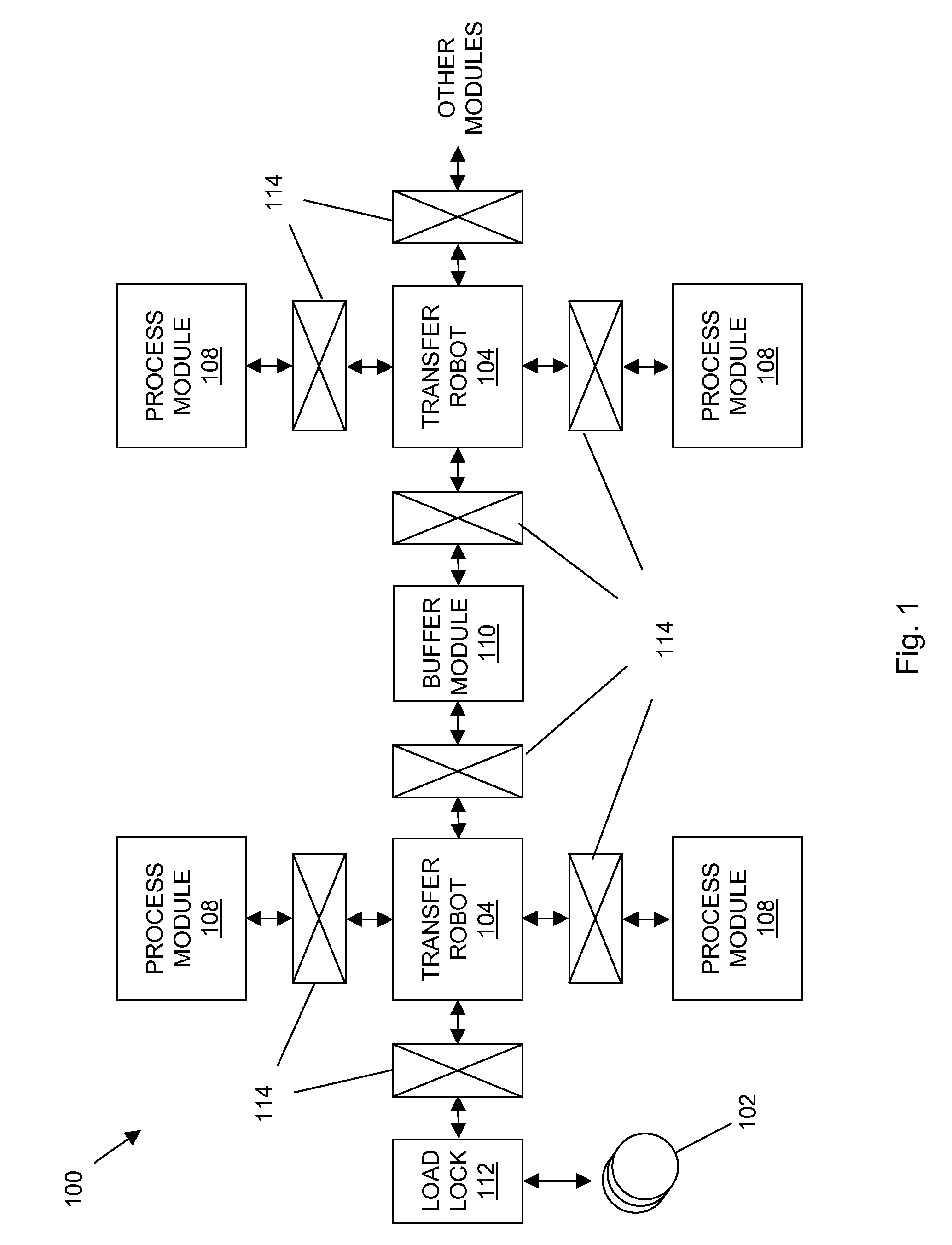
[0046]FIG. 1 shows a generalized layout of a semiconductor manufacturing system. The system 100 may include one or more wafers 102, a load lock 112, one or more transfer robots 104, one or more process modules 108, one or more buffer modules 110, and a plurality of slot valves 114 or other isolation valves for selectively isolated chambers of the system 100, such as during various processing steps. In general operation, the system 100 operates to process wafers for use in, for example, semiconductor devices.

[0047]Wafers 102 may be moved from atmosphere to the vacuum environment through the load lock 112 for processing by the process modules 108. It will be understood that, while the following description is generally directed to wafers, a variety of other objects may be handled within the system 100 including a production wafer, a test wafer, a cleaning wafer, a calibration wafer, or the like, as well as other substrates (such as for reticles, magnetic heads, flat panels, and the li...


PUM


Abstract

A variety of process modules are described for use in semiconductor manufacturing processes.

Description

CROSS-REFERENCE TO RELATED APPLICATIONS[0001]This application is a continuation-in-part of U.S. application Ser. No. 11 / 679,829 filed on Feb. 27, 2007, which claims the benefit of U.S. Prov. App. No. 60 / 777,443 filed on Feb. 27, 2006, and is a continuation-in-part of U.S. application Ser. No. 10 / 985,834 filed on Nov. 10, 2004 which claims the benefit of U.S. Prov. App. No. 60 / 518,823 filed on Nov. 10, 2003 and U.S. Prov. App. No. 60 / 607,649 filed on Sep. 7, 2004.[0002]This application also claims the benefit of the following U.S. applications: U.S. Prov. App. No. 60 / 779,684 filed on Mar. 5, 2006; U.S. Prov. App. No. 60 / 779,707 filed on Mar. 5, 2006; U.S. Prov. App. No. 60 / 779,478 filed on Mar. 5, 2006; U.S. Prov. App. No. 60 / 779,463 filed on Mar. 5, 2006; U.S. Prov. App. No. 60 / 779,609 filed on Mar. 5, 2006; U.S. Prov. App. No. 60 / 784,832 filed on Mar. 21, 2006; U.S. Prov. App. No. 60 / 746,163 filed on May 1, 2006; U.S. Prov. App. No. 60 / 807,189 filed on Jul. 12, 2006; and U.S. Prov....

Claims


Application Information

Patent Timeline
Patent Type & Authority Applications(United States)
IPC IPC(8): H01L21/677
CPCB65G25/02B65G37/00H01L21/67161H01L21/6719H01L21/67196Y10S414/139H01L21/67745H01L21/67748H01L21/67772H01L21/68792H01L21/67703H01L21/67742
Inventor VAN DER MEULEN, PETERKILEY, CHRISTOPHER C.PANNESE, PATRICK D.
Owner BOOKS AUTOMATION US LLC
Why Eureka
Try Eureka