
Fuel Cell With Hydrogen Internal Recirculation

a fuel cell and internal recirculation technology, applied in the direction of cell components, electrochemical generators, separation processes, etc., can solve the problems of abnormal mechanical solicitation of the delicate ion-exchange membrane whose lifetime may thus be shortened, and the excess of hydrogen must be exploited

Active Publication Date: 2008-05-29
NUVERA FUEL CELLS LLC
View PDF2 Cites 1 Cited by
  • Summary
  • Abstract
  • Description
  • Claims
  • Application Information

AI Technical Summary

Problems solved by technology

Such type of gas is affected by two important drawbacks, namely the presence of residual traces of carbon monoxide, which is in fact an unavoidable intermediate compound in the conversion of hydrocarbons or alcohols into hydrogen, and the need of purging remarkable quantities of gas from the fuel cell to prevent an intolerable build-up of carbon monoxide and nitrogen in its interior.
Considerable purge flow-rates pose the problem of the utilisation of the hydrogen contained therein, for instance as fuel of the steam reforming reactor in automotive applications or as fuel for the generation of thermal energy in residential-type applications, in both cases with sensible complications of the overall system.
Nevertheless this operating mode, known to those skilled in the art as “dead-end mode”, introduces at least two kinds of problems.
The former problem is associated to the capacity of the nitrogen contained in the air on the fuel cell cathode compartment to diffuse across the ion-exchange membrane, progressively building up in the stagnant hydrogen present on the anode side, particularly near the bottom: the consequent hydrogen dilution determines a preferential distribution of the output current in those zones with a less relevant presence of nitrogen, with a consequent performance decay and a possible lifetime decrease.
The latter problem is caused by the presence of liquid water formed by condensation of the water vapour transported by diffusion from the cathode compartment, similarly to what occurs with nitrogen.
The progressive liquid water build-up leads to flooding phenomena of the porous anode catalyst structure, with an additional performance decay which sums up to the one induced by the accumulation of nitrogen.
This method, however, is effective with fuel cells operating under pressure, since only in this situation the decompression caused by the purging permits a deep renewal of the anodic gas: the decompression taking place in this way nevertheless determines an abnormal mechanical solicitation of the delicate ion-exchange membrane whose lifetime may thus be shortened.
The excess of hydrogen must however be exploited, with the consequent complications of the overall system, as already mentioned for the case of feeding with gas mixtures produced in modifiers.
The individual fuel cells in which this negative situation takes place are consequently characterised by lower performances, which in extreme cases may even lead the whole stack to be put out of service.
This problem, hard to counteract in a system consisting of a multiplicity of components, moreover adds up to the negative aspect of the energy consumption of the recirculation pump.

Method used


Image

  • Fuel Cell With Hydrogen Internal Recirculation
  • Fuel Cell With Hydrogen Internal Recirculation
  • Fuel Cell With Hydrogen Internal Recirculation

Examples


first embodiment

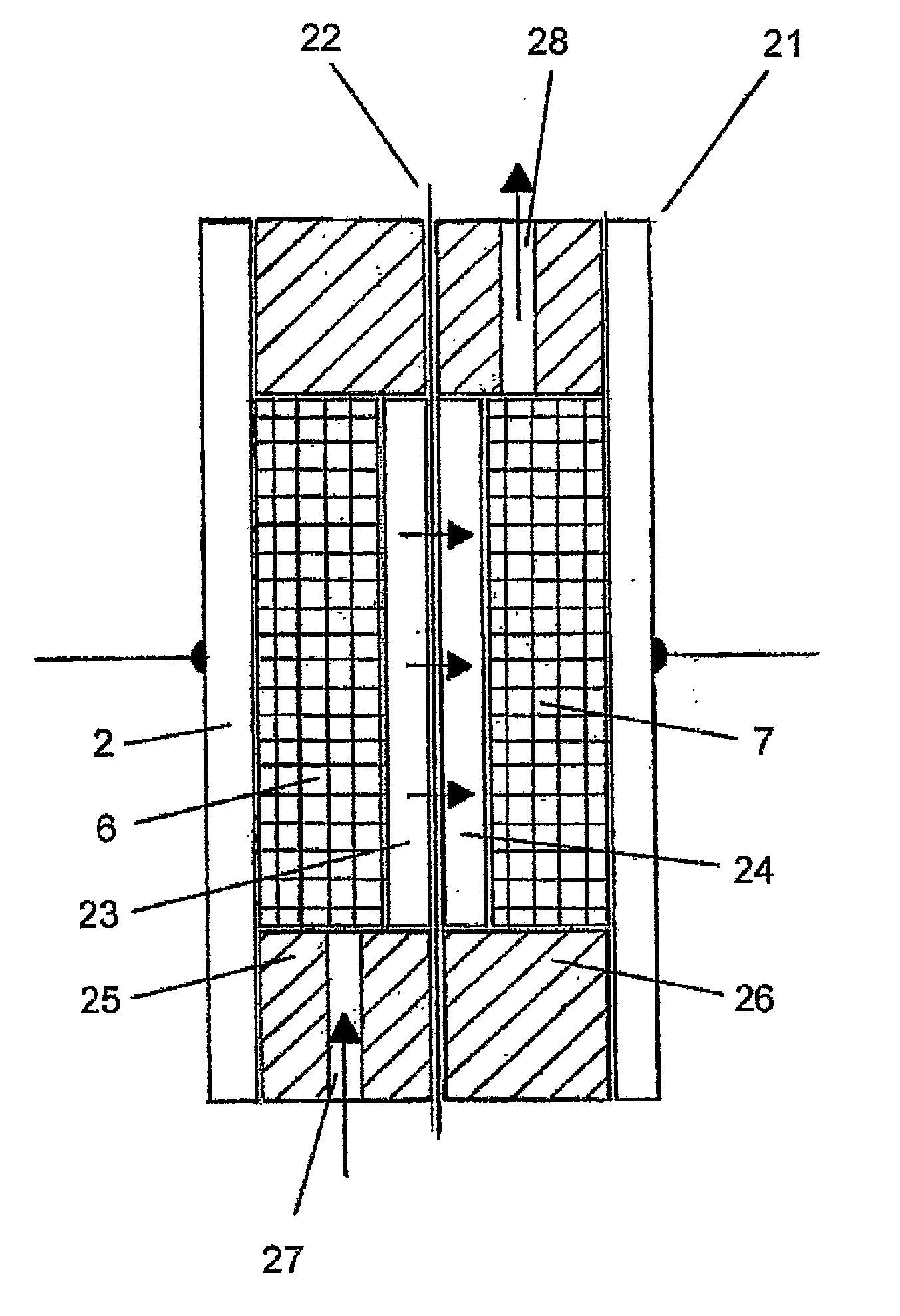
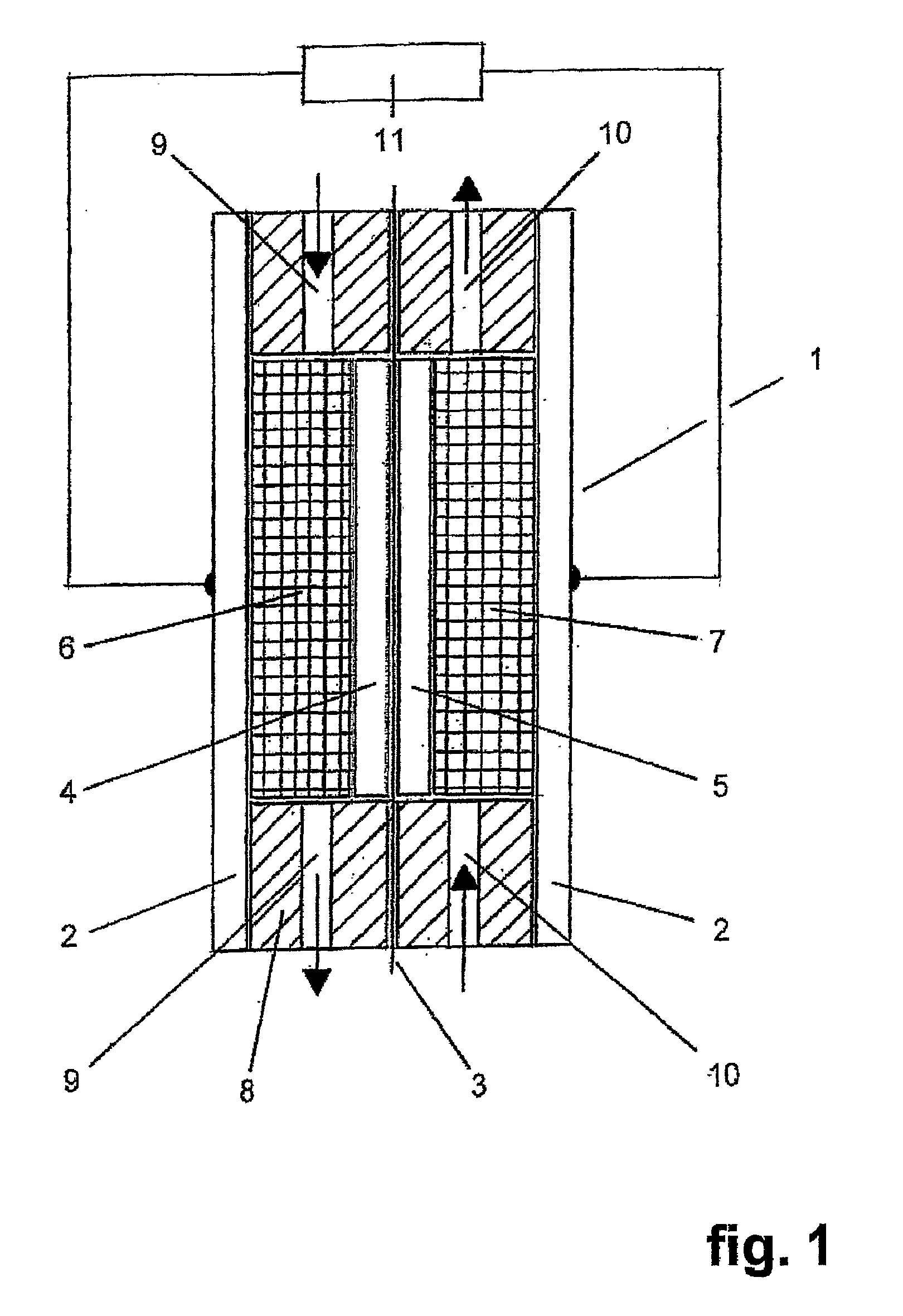
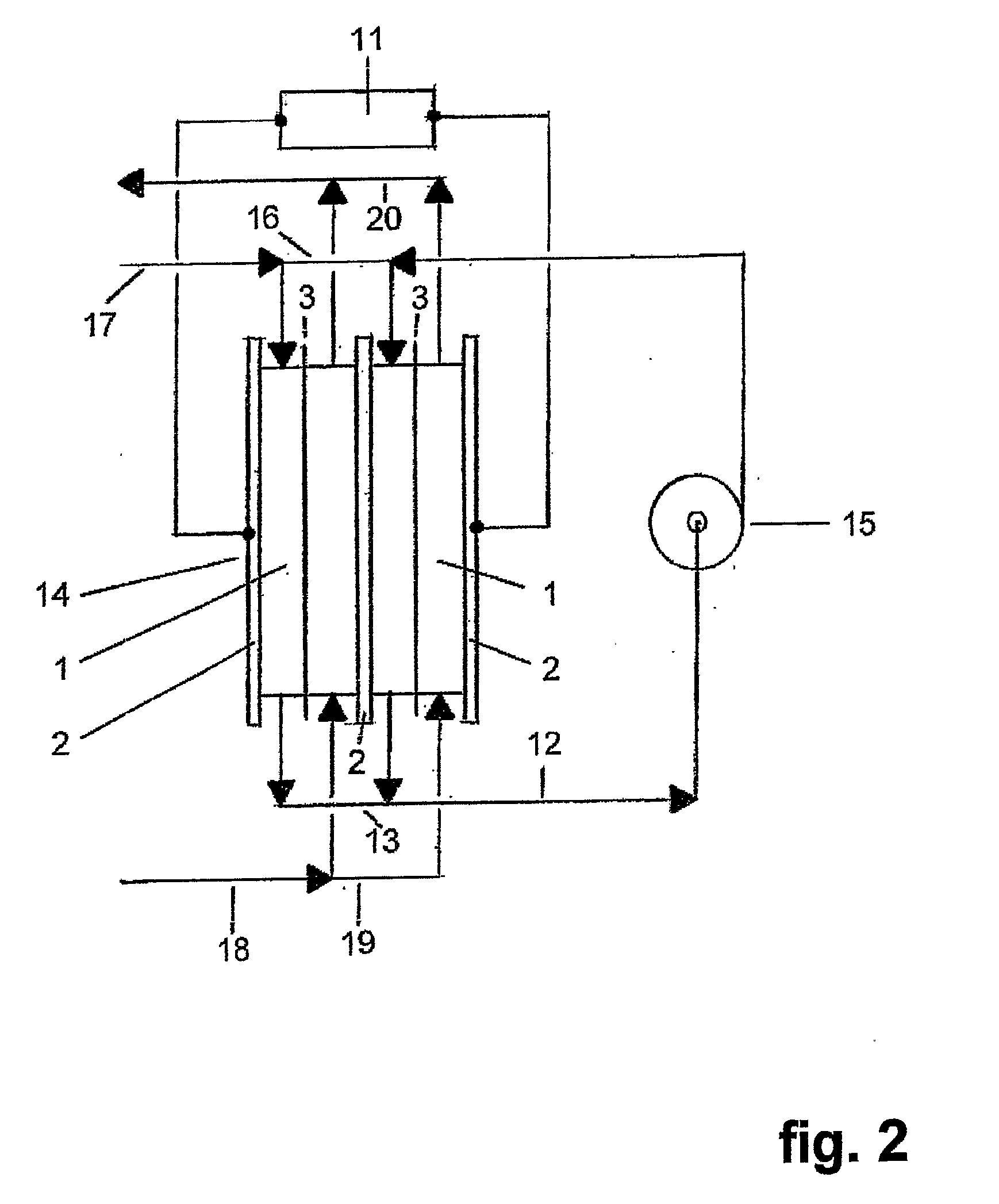
[0033]the invention is represented in FIG. 6, which sketches a side-view of a stack comprising, only for the sake of graphic simplification, two units each consisting of a fuel cell (1) of the type of FIG. 1 co-laminated and integrated with a hydrogen-transfer cell (21) of FIG. 3.

[0034]The side-view of the stack is partially represented in section and shows the integration in accordance with the invention between the components of a hydrogen-transfer cell (21) and an adjacent fuel cell (1): in particular, the cathodic current collector of the hydrogen-transfer cell also constitutes the fuel cell anodic current collector and hence the hydrogen-transfer cell (21) cathode compartment acts as the fuel cell (1) anode compartment. As a consequence, the gap comprised between two consecutive bipolar plates results subdivided into three portions, respectively, proceeding from left to right: hydrogen-transfer cell anode compartment; hydrogen-transfer cell cathode compartment coinciding with t...

second embodiment

[0035]the invention is represented in FIG. 7, which sketches a side-view of a stack comprising two units, each consisting of a fuel cell (1) of the type of FIG. 1 mechanically associated by common lamination with a hydrogen-transfer electrochemical cell (21) of FIG. 3. The partial section of the side-view shows that the hydrogen-transfer cell (21) and the adjacent fuel cell (1), comprised between two external bipolar plates, maintain their identity being kept separate by a further intermediate bipolar plate. In this case the integration between the hydrogen-transfer cell and the fuel cell is of functional type: the hydrogen produced at the cathode (24) of the hydrogen-transfer cell is in fact injected into the fuel cell anode compartment through a series of aligned holes, indicated as (29), on the intermediate bipolar plate. in particular, the recycled hydrogen is not sent to the external distributing manifold (16) as occurs in the prior art. Hence, also with the latter constructive...


PUM

PropertyMeasurementUnit
pressureaaaaaaaaaa
operating temperaturesaaaaaaaaaa
pressureaaaaaaaaaa

Abstract

A unit consisting of a fuel cell, provided with a first ion-exchange membrane, and an electrolysis cell, equipped with a second ion-exchange membrane, capable of operating as an electrochemical hydrogen pump in which the electrolysis cell sucks in the discharge gas of the fuel cell anodic compartment which contains hydrogen as the main component, ionizes the hydrogen on a suitable anodic catalyst, sends the so formed protons across the second ion-exchange membrane to a suitable cathodic catalyst where the protons are reconverted to hydrogen which is mixed to the fuel cell hydrogen feed.

Description

BACKGROUND OF THE INVENTION[0001]Fuel cells are devices characterised by the possibility of converting the chemical energy of combination of a fuel and an oxidant directly into electrical energy. For this reason, fuel cells are not subject to the known limitation of Carnot's cycle, based on an intermediate thermal stage, and are therefore characterised by a high energy efficiency.[0002]Among the several types under development at present, ion-exchange membrane fuel cells are considered of peculiar interest for automotive and for medium-small size residential generation applications, due to the compactness, the relative operating simplicity and the absence of important decay phenomena in the construction materials.[0003]The oxidant normally employed in ion-exchange membrane fuel cells is air, at near-atmospheric pressure or under a pressure not exceeding 3-4 bar. The fuel, fed at about the same pressure as air, may consist of a gas containing hydrogen together with other components s...

Claims


Application Information

Patent Timeline
Patent Type & Authority Applications(United States)
IPC IPC(8): H01M8/02
CPCB01D53/32H01M8/04097Y02E60/50H01M8/065H01M8/04231Y10S204/04
Inventor FACCHI, DANIELE
Owner NUVERA FUEL CELLS LLC
Learn More