Maximum Entropy Signal Detection Method

Active Publication Date: 2008-05-29
CANBERRA IND INC
View PDF2 Cites 0 Cited by
  • Summary
  • Abstract
  • Description
  • Claims
  • Application Information

AI Technical Summary

Problems solved by technology

Detecting radioactivity in dynamic situations—where the radiation signal is varying with time—is problematic, if the goal is to detect the smallest true signal, and at the same time not generate a “detection” signal if there is no signal present.
The problem with this method is to determine the most appropriate time window.
If it is made too wide, or too narrow, with respect to the time-varying signal, the detection levels will be not as good as they can be.
Too wide a window includes more noise than optimum, and reduces the ability to detect small sources.
Too narrow a window eliminates much of the signal, and reduces the ability to detect small sources.
A similar problem occurs if there are multiple sensors viewing an object where the signal from the object is not the same as viewed by each of the detectors.
This can be because the radioactivity in the object is not uniform—some of it is closer to certain detectors than to other detectors, or obscured by more attenuating material between the radioactivity and the detectors.
The problem is to determine the most appropriate combination of detectors to allow detection of the smallest amount of radioactivity present in the object.
Using too many detectors includes too much background noise, and reduces the ability to detect small sources; using too few detectors eliminates useful signal, and reduces the ability to detect small sources.
It is now very difficult to make an a-priori estimate of the proper time window and detector grouping for the optimum summation to allow detection of the lowest level of radioactivity.

Method used


Image

  • Maximum Entropy Signal Detection Method
  • Maximum Entropy Signal Detection Method

Examples


Embodiment Construction

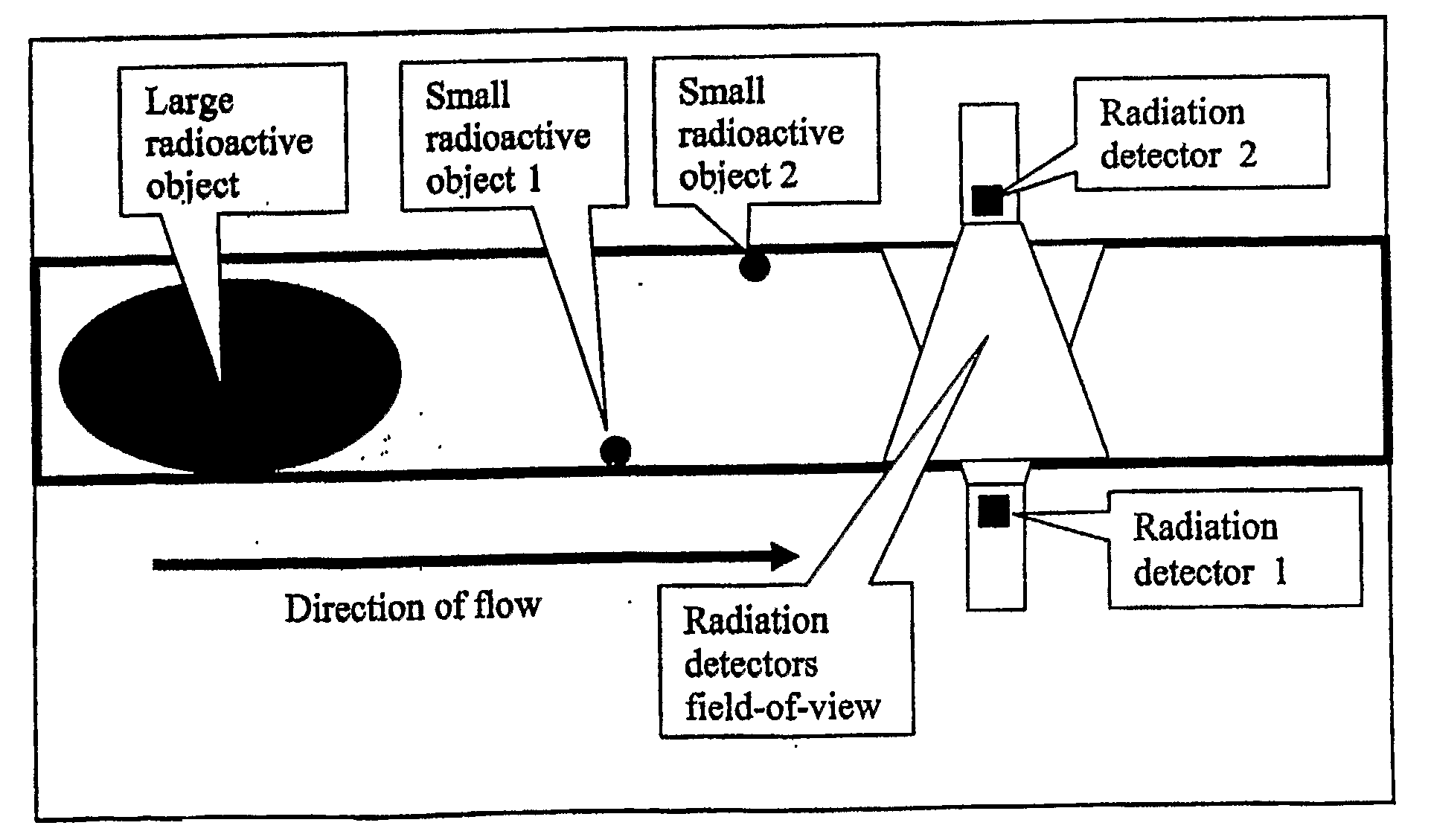
[0018]Since an a priori understanding of what combination of sample window and detector grouping and energy window provides the optimal sensitivity is not possible, testing is conducted at all reasonable combinations of these items. Possible detector groupings, for example where 3 detectors are used, include 1; 2; 3; 1 & 2; 1 & 3; 2 & 3; and 1 & 2 & 3. A sample analysis window is established, based on the upper bound signal change rate, referred to as a Basic Interval. Analysis windows are established as integer multiples of the Basic Interval, from a single Basic Interval to the longest window made necessary by the lower bound of the signal change rate. In practice, each detector acquires units of data for Basic Intervals. In the case of spectroscopy detectors, multiple energy regions may be defined. A matrix of the combinations of detector groupings, sample windows, and energy windows is established. An appropriate statistical detection threshold is tested for each combination. As...


PUM


Abstract

Methods of detecting radioactivity in dynamic situations in which radiation is detected from large and small radioactive objects with at least one radiation detector as the objects pass through the field of view and combinations are made from those measurements which are either adjacent in time, from multiple detectors, or at different energies. An elevated signal is reported when an analysis of the various combinations shows an elevated signal in any one combination. Small amounts of radioactivity can be detected even in the presence of large amounts.

Description

TECHNICAL FIELD[0001]The present invention relates to signal detection generally including but not limited to a novel method for detecting radioactivity in dynamic situations that is used as an example of reducing the method to practice.BACKGROUND ART[0002]Detecting radioactivity in dynamic situations—where the radiation signal is varying with time—is problematic, if the goal is to detect the smallest true signal, and at the same time not generate a “detection” signal if there is no signal present. This time variance of the radioactivity signal can be for many different reasons. Common ones include:[0003]small segments of radioactivity mixed with normal material moving down a pipe or conveyor belt past one or more fixed radiation detectors;[0004]radioactivity in a vehicle moving past one or more fixed radiation detectors;[0005]one or more radiation detectors moving past radioactive objects.[0006]The normal method of signal analysis is to establish a noise or background level for the...

Claims


Application Information

Patent Timeline
IPC IPC(8): G06F19/00
CPCG01T1/167
Inventor BRONSON, FRAZIERRUSS, WILLIAM
Owner CANBERRA IND INC
Why Eureka
Try Eureka