Multichannel Decorrelation In Spatial Audio Coding

Active Publication Date: 2008-05-29
DOLBY LAB LICENSING CORP
View PDF29 Cites 58 Cited by
  • Summary
  • Abstract
  • Description
  • Claims
  • Application Information

AI Technical Summary

Benefits of technology

[0013]According to other aspects of the invention, each decorrelating filter characteristic may be characterized by a model with multiple degrees of freedom. Each decorrelating filter characteristic may have a response in the form of a frequency varying delay where the delay decreases monotonically with increasing frequency. The impulse response of each

Problems solved by technology

In the decoder, application of the interchannel amplitude and time or phase differences is relatively straightforward, but modifyin

Method used


Image

  • Multichannel Decorrelation In Spatial Audio Coding
  • Multichannel Decorrelation In Spatial Audio Coding
  • Multichannel Decorrelation In Spatial Audio Coding

Examples


Embodiment Construction

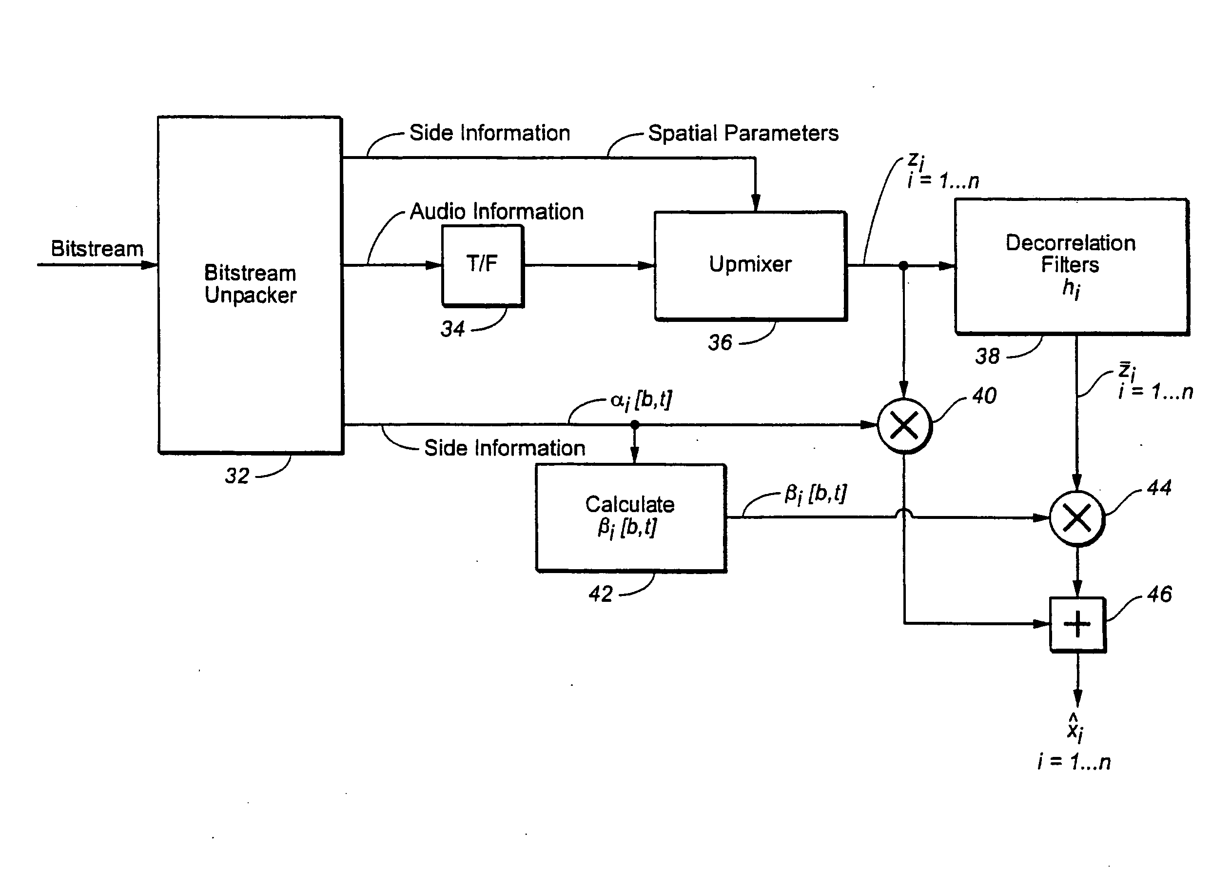
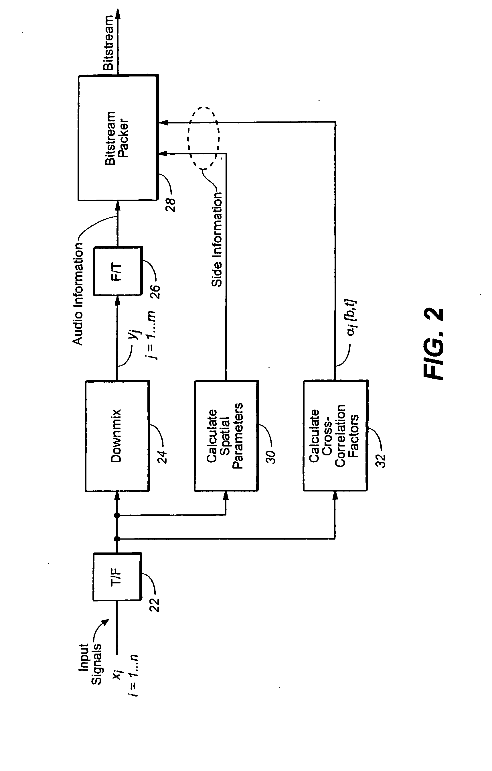
[0017]Referring to FIGS. 2 and 3, the original N audio signals are represented by xi, i=1 . . . N. The M downmixed signals generated at the encoder are represented by yj, j=1 . . . M. The first set of upmixed signals generated at the decoder through application of the interchannel amplitude and time or phase differences is represented by zi, i=1 . . . N. The second set of upmixed signals at the decoder is represented by zi, i=1 . . . N. This second set is computed through convolution of the first set with the decorrelation filters:

zi=hi*zi,  (1)

where hi is the impulse response of the decorrelation filter associated with signal i. Lastly, the approximation to the original signals is represented by {circumflex over (x)}i, i=1 . . . N. These signals are computed by mixing signals from the described first and second set in a time and frequency varying manner:

{circumflex over (X)}i[b,t]=αi[b,t]Zi[b,t]+βi[b,t] Zi[b,t],  (2)

where Zi[b,t], Zi[b,t], and {circumflex over (X)}i[b,t] are the sh...


PUM


Abstract

Each of N audio signals are filtered with a unique decorrelating filter (38) characteristic, the characteristic being a causal linear time-invariant characteristic in the time domain or the equivalent thereof in the frequency domain, and, for each decorrelating filter characteristic, combining (40, 44, 46), in a time and frequency varying manner, its input (Zi) and output (Z-i) signals to provide a set of N processed signals (X i). The set of decorrelation filter characteristics are designed so that all of the input and output signals are approximately mutually decorrelated. The set of N audio signals may be synthesized from M audio signals by upmixing (36), where M is one or more and N is greater than M.

Description

TECHNICAL FIELD[0001]The present invention relates to audio encoders, decoders, and systems, to corresponding methods, to computer programs for implementing such methods, and to a bitstream produced by such encoders.BACKGROUND ART[0002]Certain recently-introduced limited bit rate coding techniques analyze an input multi-channel signal to derive a downmix composite signal (a signal containing fewer channels than the input signal) and side-information containing a parametric model of the original sound field. The side-information and composite signal are transmitted to a decoder that applies the parametric model to the composite signal in order to recreate an approximation of the original sound field. The primary goal of such “spatial coding” systems is to recreate a multi-channel sound field with a very limited amount of data; hence this enforces limitations on the parametric model used to simulate the original sound field. Details of such spatial coding systems are contained in vari...

Claims


Application Information

Patent Timeline
IPC IPC(8): G10L21/04
CPCG10L19/008G10L19/02
Inventor SEEFELDT, ALAN JEFFREYVINTON, MARK STUART
Owner DOLBY LAB LICENSING CORP
Why Eureka
Try Eureka