
Method of refreshing a dynamic random access memory and corresponding dynamic random access memory device, in particular incorporated into a cellular mobile telephone

Inactive Publication Date: 2008-05-29
STMICROELECTRONICS SRL
View PDF6 Cites 68 Cited by
  • Summary
  • Abstract
  • Description
  • Claims
  • Application Information

AI Technical Summary

Benefits of technology

[0009]An object of the invention is to provide a dynamic random access memory refresh device which has not been made to undergo any burn-in operation, but the refresh period may be adjusted, such as in an optimal manner, so as to limit the power consumption of the device.
[0010]Another object is to further reduce the power consumption brought about by the refreshing of the memory, in particular, by improving the test performed at the memory cell level. As the mechanism for measuring the retention may be somewhat slow (this not posing a problem if the temperature increases slowly), another object is to reduce problems appearing if the temperature rises more quickly than the system measuring the retention, given that temperature influences the retention time of the memory cells.
[0015]Indeed, the use of an error correction system makes it possible to ignore a certain number of errors (according to the number of errors that the error correction system in question is capable of correcting), since each time the erroneous data item is transferred out of the memory, the system may automatically correct these errors.
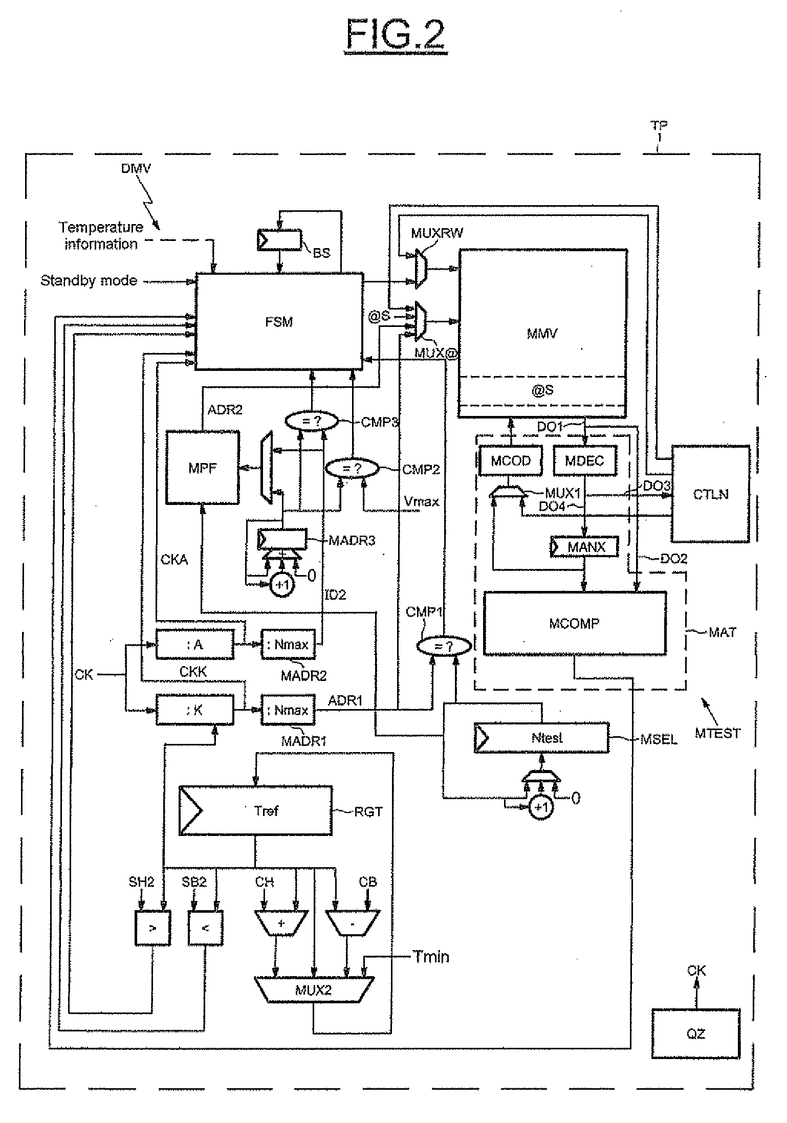
[0023]The device comprises increase means or a refresh controller able to increase the value of the memory refresh frequency, if the number of groups of memory cells comprising at least one erroneous packet is greater than a fixed threshold. According to an embodiment, the safe memory area comprises a reserved area of the random access memory, refreshed at the maximum value of the refresh frequency, so as to save the model group. According to another embodiment, the safe memory area comprises an ancillary static memory coupled to the dynamic random access memory, so as to save the model group.
[0026]The device can further comprise comparison means or a comparer being able to compare the fill of the weak pages memory and the threshold. The device can further comprise recording means or a recorder being able to record the effecting of an increase in the frequency. The device can further comprise reduction means or a second refresh controller coupled to the recording means, and able to reduce the refresh frequency.

Problems solved by technology

Third-generation cellular mobile telephones may use the integration of large quantities of memory; however, the cost of the product may yet remain low.
However, an important constraint in this type of application may be the need to provide a low level of power consumption while the telephone is on standby, so as not to discharge the batteries too quickly.
More precisely, for a group of selected memory cells, the number of accumulated errors is observed when the refresh frequency of these memory cells is decreased.
However, in addition to the errors related to the junction leaks in the transistors of the memory cells, some errors are due to hardware defects in the memory cell, and to the wear and tear of the components in the memory, for example.
In the absence of a prior burn-in operation, errors due to defective memory cells, for example, ones having an extremely low retention time, could appear during the use of the memory on a certain number of items, thus degrading the product quality level.
However, though the burn-in operation is beneficial for eliminating circuits comprising the aforesaid defective memory cells, burn-in may be particularly expensive.
Another drawback may reside in a generally performed test of the memory cell.

Method used


Image

  • Method of refreshing a dynamic random access memory and corresponding dynamic random access memory device, in particular incorporated into a cellular mobile telephone
  • Method of refreshing a dynamic random access memory and corresponding dynamic random access memory device, in particular incorporated into a cellular mobile telephone
  • Method of refreshing a dynamic random access memory and corresponding dynamic random access memory device, in particular incorporated into a cellular mobile telephone

Examples


Embodiment Construction

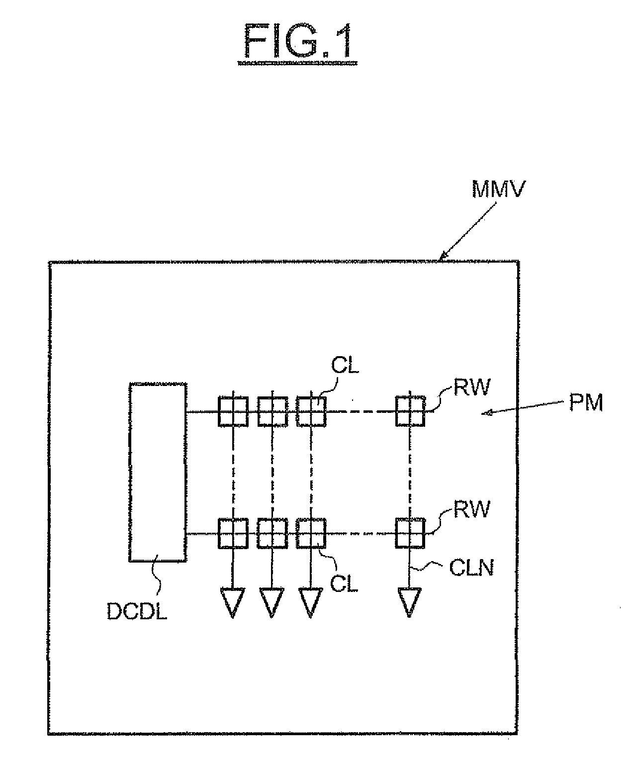
[0041]In FIG. 1, the reference MMV designates a dynamic random access memory whose memory plane PM comprises a matrix array of memory cells CL typically organized in rows RW and columns CLN. Each memory cell generally comprises a transistor and a capacitor. Additionally, in a conventional manner known, the memory plane PM is connected to a row decoder DCDL and to a column decoder (which are not represented here for simplifying purposes).

[0042]In a general manner, the retention time of all the cells of the memory may be measured continuously and dynamically on the chip (integrated circuit) containing the memory MMV, and the refresh period of this memory may be adjusted accordingly. In the example described herein, the memory is organized into memory pages, a page corresponding to a line of words.

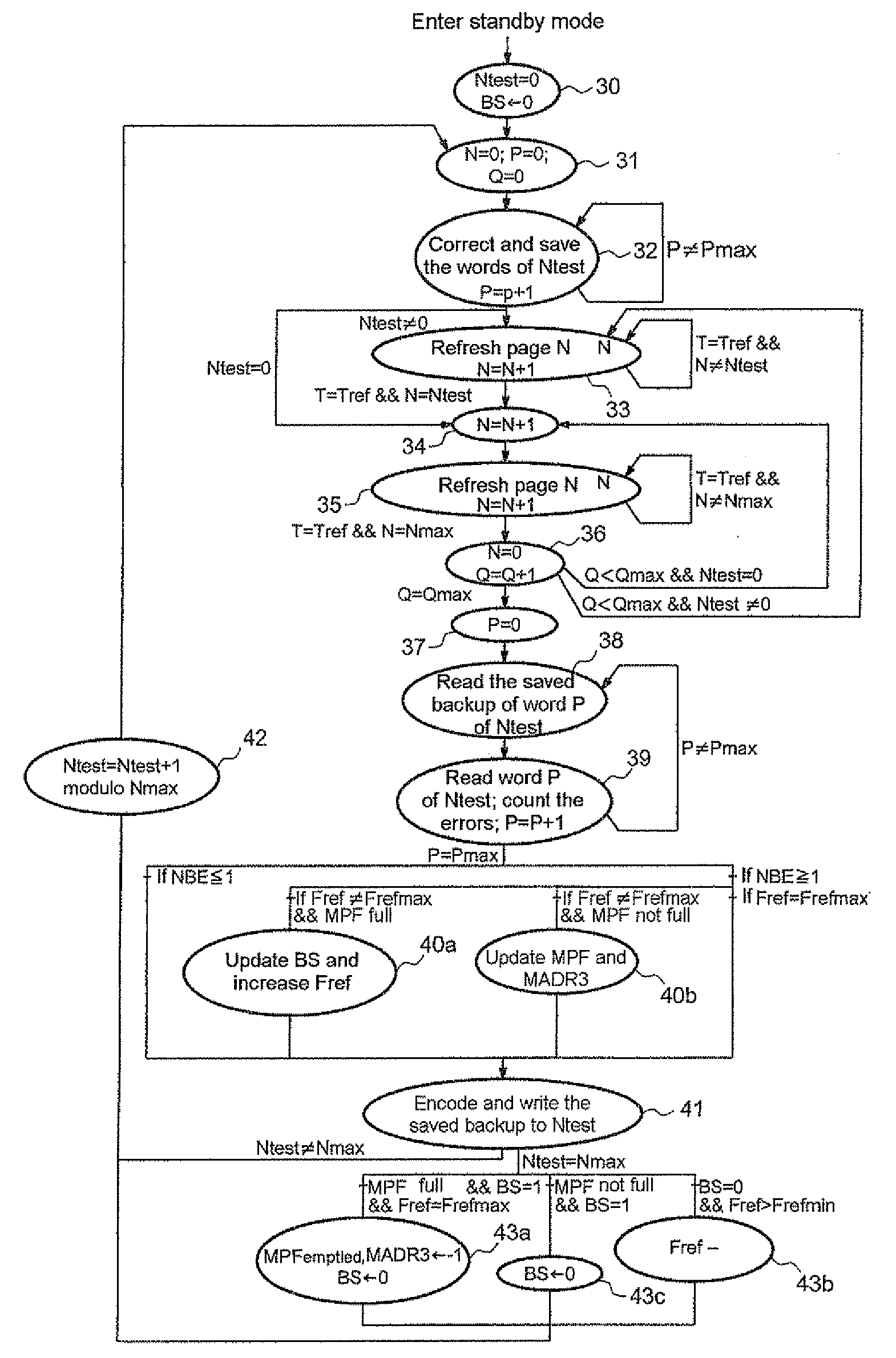
[0043]Also, before returning in greater detail to the algorithm for adjusting the refresh period, we may forthwith describe the basic outline of a mode of implementation thereof which compris...


PUM


Abstract

A method is for refreshing a dynamic random access memory coupled to an error correction system, which uses an error correcting code. The dynamic random access memory includes groups of memory cells storing bits, each group of memory cells being subdivided into packets of memory cells. Each packet of memory cells is supplemented with the error correcting code. The method includes performing a retention test on each group of memory cells, and increasing a memory refresh frequency if a number of test groups of memory cells having at least one erroneous packet is greater than a threshold.

Description

FIELD OF THE INVENTION[0001]The invention relates to dynamic random access memories, that is to say, those using periodic refreshing of the data stored in the memory cells of these memories, and more particularly, to the refreshing of these dynamic random access memories.BACKGROUND OF THE INVENTION[0002]Third-generation cellular mobile telephones may use the integration of large quantities of memory; however, the cost of the product may yet remain low. The use of dynamic random access memories, in place of the static random access memories, allows this rise in memory capacity while maintaining a low cost.[0003]However, an important constraint in this type of application may be the need to provide a low level of power consumption while the telephone is on standby, so as not to discharge the batteries too quickly. However, although dynamic random access memories have a smaller static leakage current than static random access memories, they need to be refreshed continuously if the data...

Claims


Application Information

Patent Timeline
IPC IPC(8): G11C29/52G06F11/263
CPCG11C7/04G11C11/406G11C2211/4062G11C2211/4061G11C11/40626
Inventor HARRAND, MICHEL
Owner STMICROELECTRONICS SRL
Learn More