Method and apparatus for solar heating air in a forced draft heating system

Inactive Publication Date: 2008-06-05
BURTON ANDY
View PDF4 Cites 40 Cited by
  • Summary
  • Abstract
  • Description
  • Claims
  • Application Information

AI Technical Summary

Benefits of technology

[0004]The present invention, which will be described subsequently in greater detail, includes a heating system for installation in a forced draft heating system to heating air flow through the ducting of the forced draft heating system. The heating system includes a solar collector assembly for heating a liquid circulated through the assembly. The heated liquid is stored in an insulated storage tank where it can be circulated through a heat exchanger positioned in an air duct of the forced draft heating system as need to heat air flow through the duct. The use of a liquid as the heat transfer flu

Problems solved by technology

In recent years, the cost of energy has increased substantially resulting in higher operation costs associated with heating a building including residential and commercial buildings a like.
In the most sever situations, the increased costs have forced limited or no operation of the building heating systems.
While the devices heretofore fulfill their respective, particular objectives and requirements, they do not provide a solar heating system that is used in combination with an existing forced draft heating system, that can be easily installed in an existing

Method used


Image

  • Method and apparatus for solar heating air in a forced draft heating system
  • Method and apparatus for solar heating air in a forced draft heating system
  • Method and apparatus for solar heating air in a forced draft heating system

Examples


Embodiment Construction

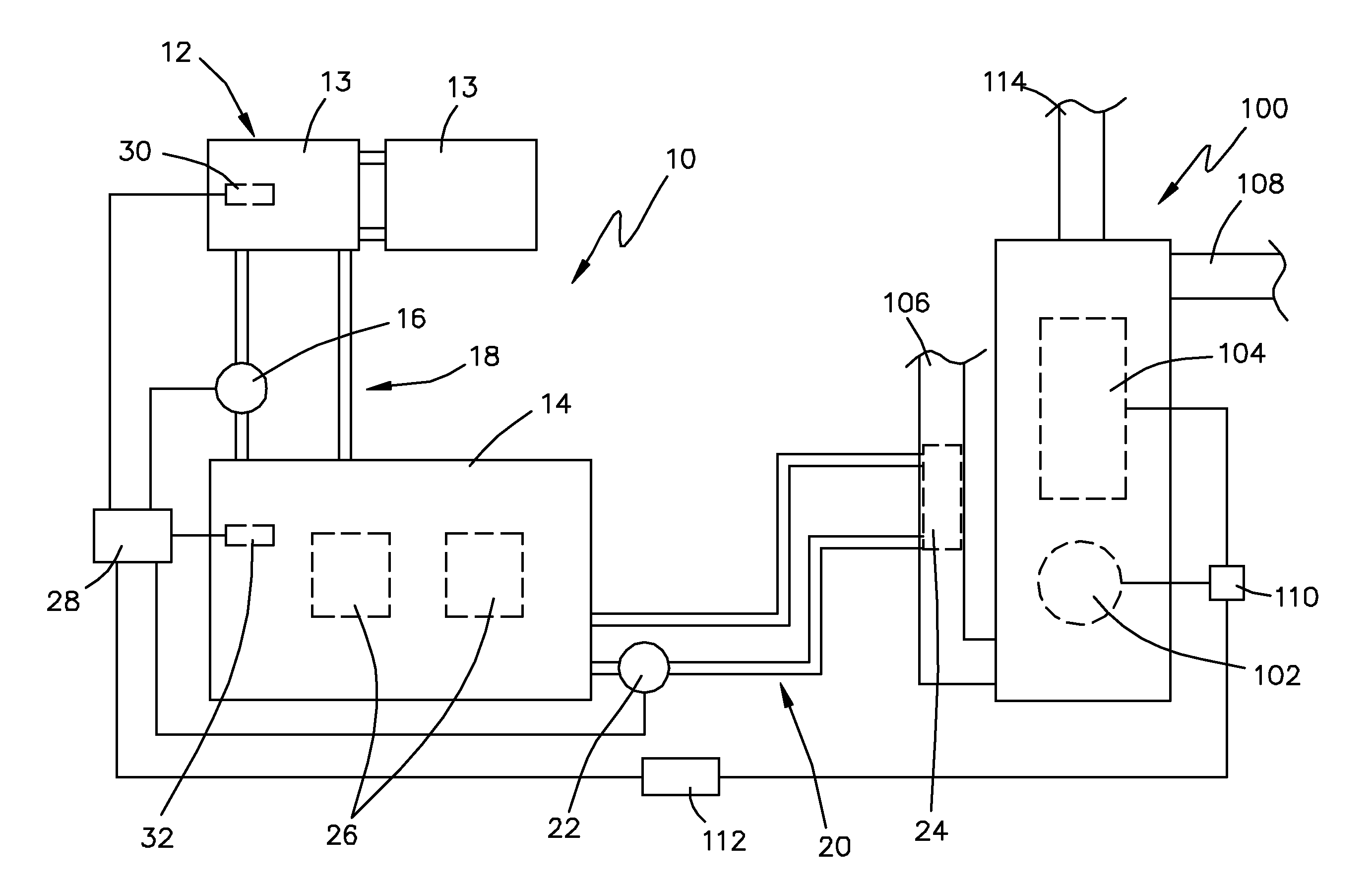
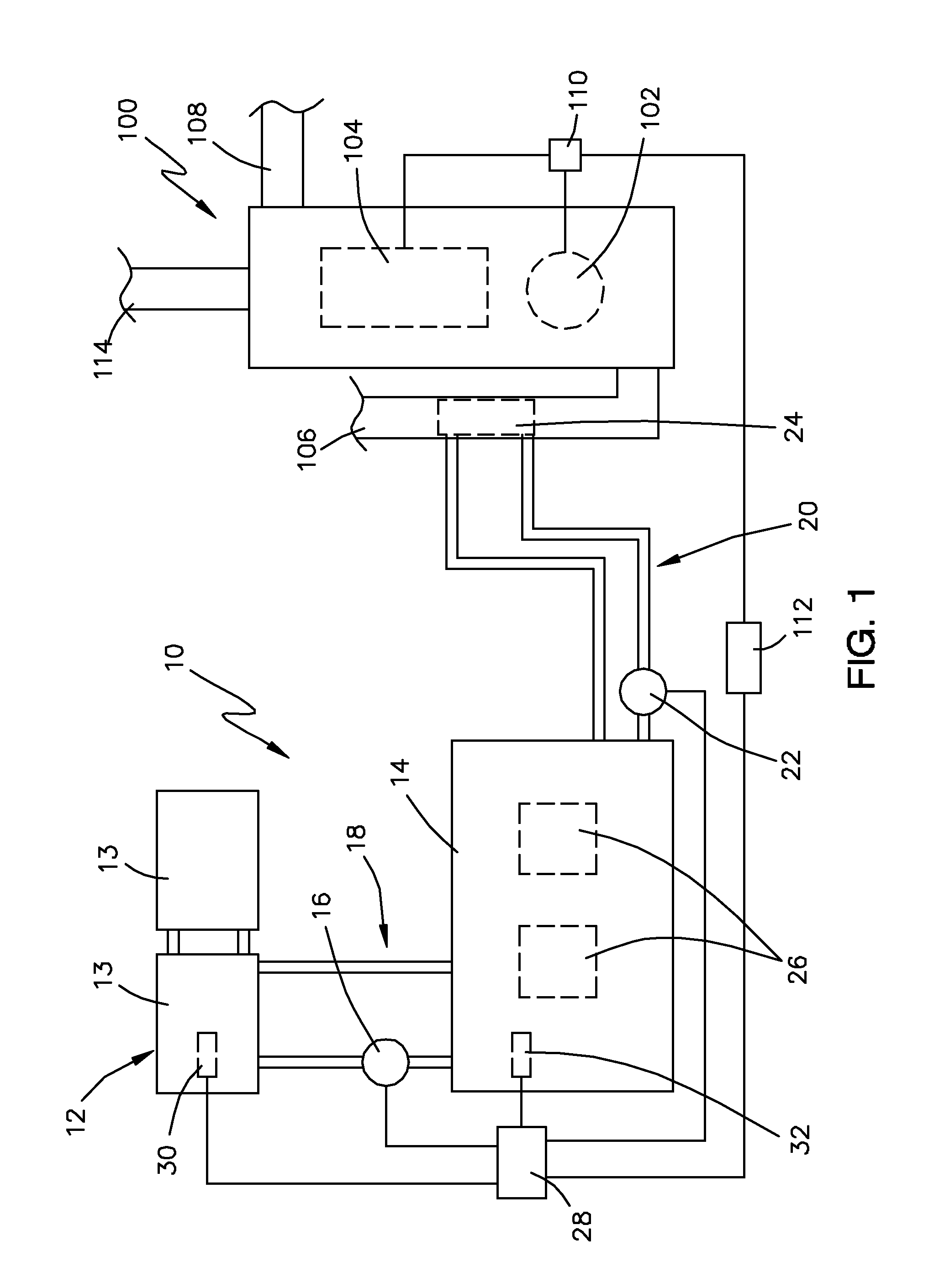
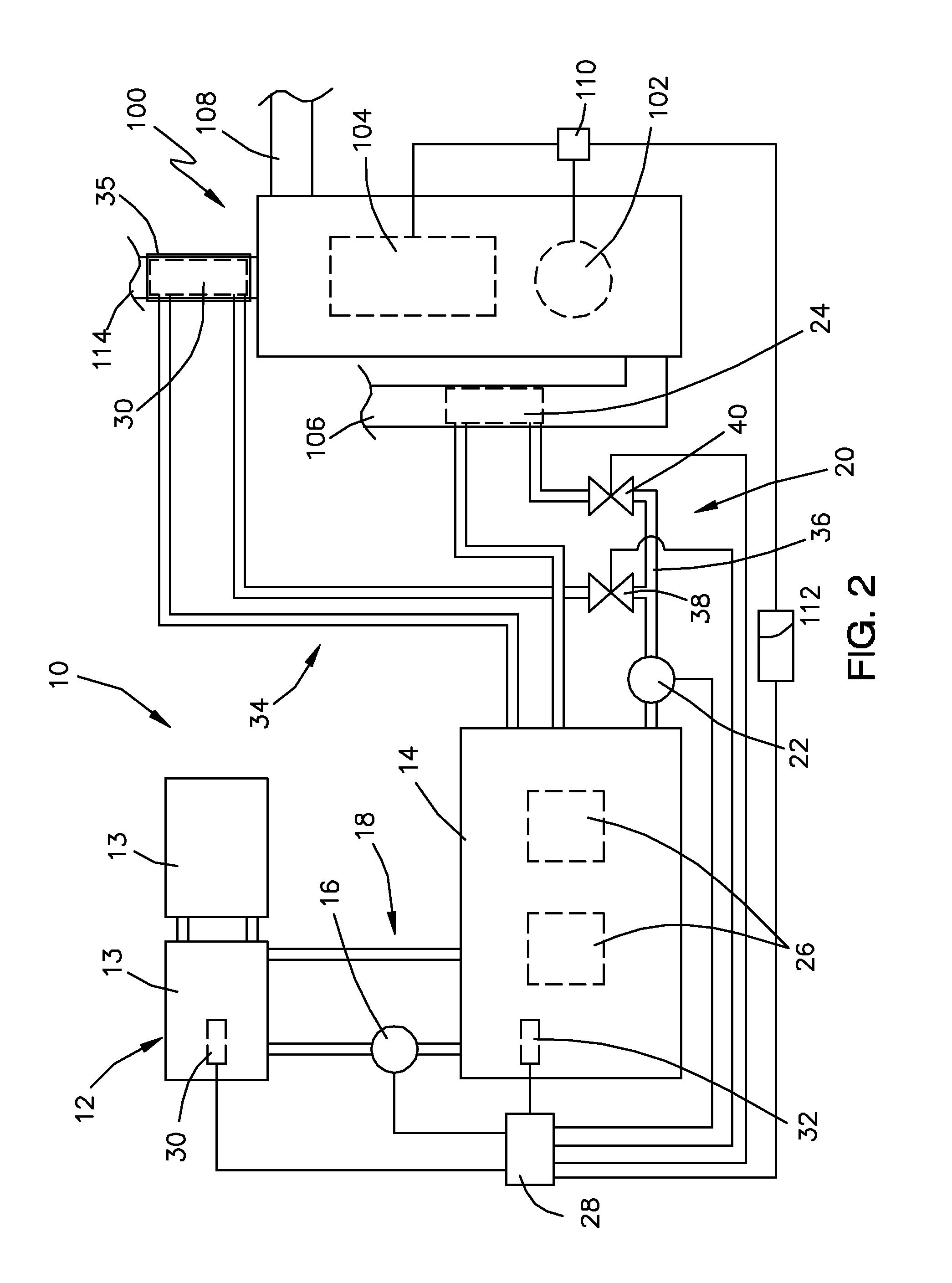
[0015]Reference will now be made in detail to the drawings. Wherever possible, the same reference numbers will be used throughout the drawings to refer to the same or like elements.

[0016]With reference to FIG. 1 there is schematically shown a solar heating system, generally designated by numeral 10, for use in combination with a forced draft heating system 100. The forced draft heating system 100 can be any forced air heating system that is used to heat ventilation air. In general, the solar heating system 10 utilizes solar energy to heat or pre-heat ventilation air flowing through an air duct of the forced draft heating system 100 to reduce energy costs associated with operating the forced draft heating system.

[0017]The forced draft heating system 100 is a typical heating system installed in residential and commercial buildings to heat the interior space of the building by heating the ventilation air. For the purpose herein, the forced draft heating system 100 will be described gen...


PUM


Abstract

A solar heating system for use in combination with a forced draft heating system for heating ventilation air of a building. The solar heating system includes a solar collector assembly for heating a liquid circulated through the assembly. The heated liquid is stored in an insulated storage tank where it can be circulated through a heat exchanger positioned in an air duct of the forced draft heating system as need to heat air flow through the duct. The use of a liquid as the heat transfer fluid and providing a storage facility for heated liquid permits the heating system to operate for a period of time after the sun sets or becomes ineffective in providing solar radiation until the heat stored in the liquid becomes exhausted. To increase the heat storage capacity of the liquid, one or more heat sinks can be utilized to absorb excess heat from the liquid and then transfer the absorbed heat back to the liquid when an opposite thermal gradient exists. Additionally, the heating system can recover waste heat from hot combustion gases exhausted from a fuel-fired forced draft heating system.

Description

FIELD OF THE INVENTION[0001]The present invention relates generally to heating of ventilation air of a building, and more particularly, to solar heating of ventilation air in an existing forced draft heating system.BACKGROUND OF THE INVENTION[0002]In recent years, the cost of energy has increased substantially resulting in higher operation costs associated with heating a building including residential and commercial buildings a like. In the most sever situations, the increased costs have forced limited or no operation of the building heating systems. It is known that solar radiation can be used for heating such buildings and an example of such devices are described in the following U.S. Pat. No. 6,880,553; 4,934,338; 4,509,503; and 4,343,296.[0003]While the devices heretofore fulfill their respective, particular objectives and requirements, they do not provide a solar heating system that is used in combination with an existing forced draft heating system, that can be easily installe...

Claims


Application Information

Patent Timeline
IPC IPC(8): F24J2/04F24S10/40
CPCF24F5/0017F24F5/0046F24F11/006Y02E70/30Y02B10/20Y02B10/24Y02E60/147F24F2005/0064F24F11/30F24F11/62Y02A30/272Y02E60/14F24F11/52
Inventor BURTON, ANDY
Owner BURTON ANDY
Why Eureka
Try Eureka