Vapor chamber heat sink having a carbon nanotube fluid interface

a carbon nanotube and heat sink technology, applied in the field of heat sinks, can solve the problems of affecting the use of heat sinks, etc., and achieve the effects of improving the use effect, improving the efficiency of heat sinks, and improving the use

Active Publication Date: 2008-06-05
SAMSUNG ELECTRONICS CO LTD
View PDF99 Cites 59 Cited by
  • Summary
  • Abstract
  • Description
  • Claims
  • Application Information

AI Technical Summary

Problems solved by technology

The fluid container is contacted to a hot surface, causing the fluid to boil.
This is of particular importance in, for example, semiconductor devices where, at relatively low surface temperatures, the structures may be permanently damaged by excess heat.
Unfortunately, the Mok et al. invention suffers from several deficiencies.
First, growing CNTs on an uneven surface that comprises grooves is complex due to different growth orientations.
Second,

Method used


Image

  • Vapor chamber heat sink having a carbon nanotube fluid interface
  • Vapor chamber heat sink having a carbon nanotube fluid interface
  • Vapor chamber heat sink having a carbon nanotube fluid interface

Examples


Embodiment Construction

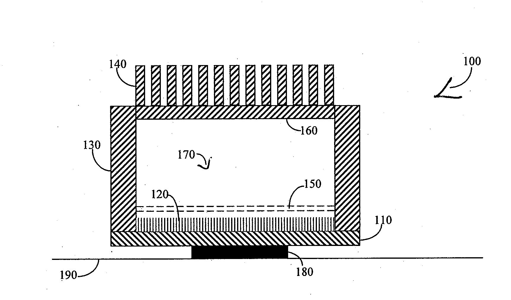
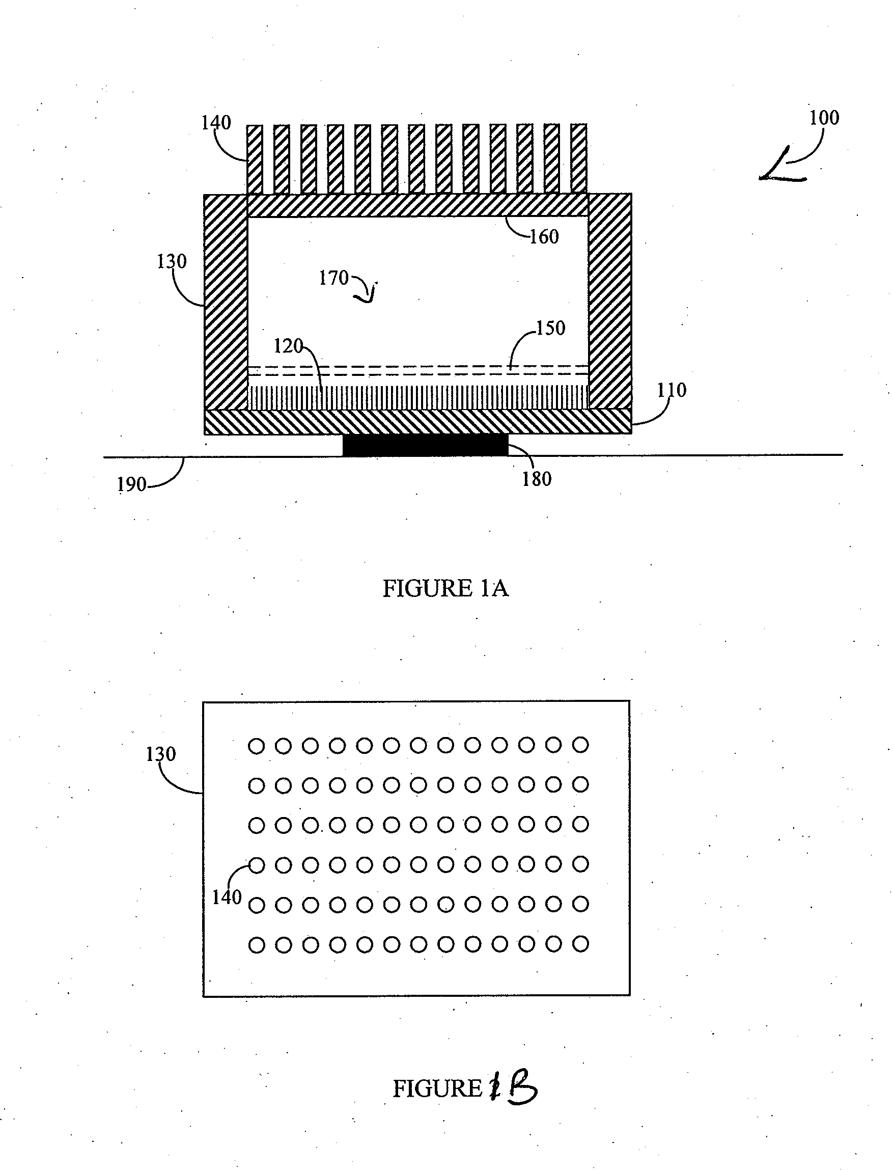
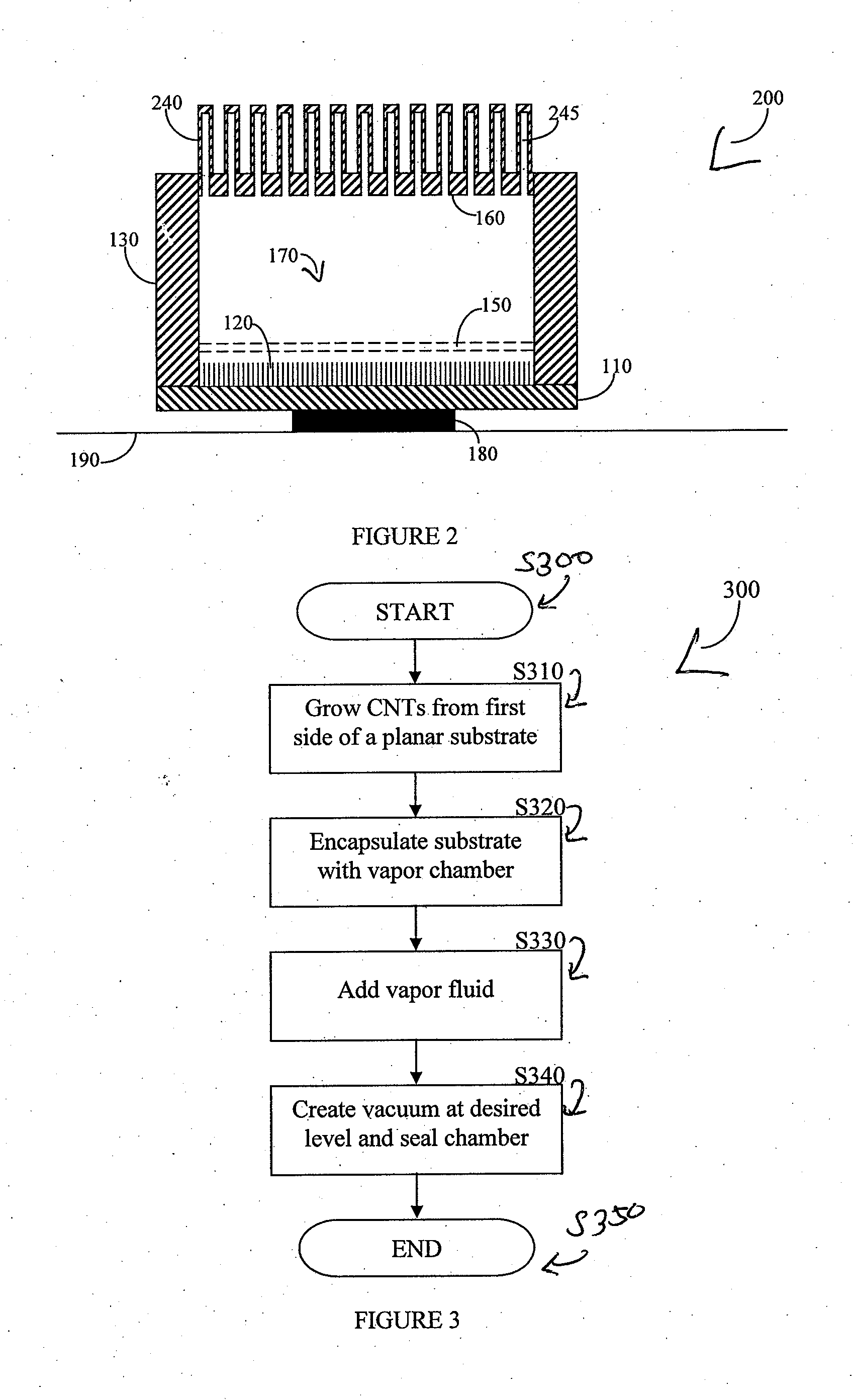
[0017]The presently preferred embodiment of the invention provides an enhanced heat transposer comprised of a vapor chamber. The surface of the vapor chamber that holds the fluid comprises an array of carbon nanotubes (CNTs) that are grown in a way that enables the fluid to come into maximum contact with the CNTs. The fluid evaporates in the sealed vapor chamber when it is in touch with a hot surface. The resulting vapor comes in contact with a hollow pin-fin structure that provides additional surface for vapor cooling and heat transfer. The condensed vapor then drops back to the fluid container, and the cycle continues.

[0018]FIGS. 1A and 1B show a first embodiment of a vapor chamber heat sink 100 according to the invention. The heat sink 100 comprises a substrate 110 and an encapsulating structure 130 that, when attached to the substrate 110 and sealed, forms a vapor chamber 170. A typical substrate thickness is between 2 and 15 millimeters. Prior to sealing, a vapor fluid 150 is a...


PUM


Abstract

An enhanced heat transposer comprised is of a vapor chamber. The surface of the vapor chamber that holds the fluid comprises an array of carbon nanotubes (CNTs) that are grown in a way that enables the fluid to come into maximum contact with the CNTs. The fluid evaporates in the sealed vapor chamber when it is in touch with a hot surface. The vapor comes in contact with a hollow pin-fin structure that provides additional surface area for vapor cooling and heat transfer. The condensed vapor then drops back into the fluid container, and the cycle continues.

Description

CROSS REFERENCE TO RELATED APPLICATIONS[0001]This application claims the benefit of: (A) U.S. provisional patent application Ser. No. 60 / 800,935, filed May 16, 2006, entitled Small-size coupons and bonded assemblies for CNT-based thermal management of IC devices; (B) U.S. provisional patent application Ser. No. 60 / 874,579, filed Dec. 12, 2006, entitled Carbon nanotube-based structures and methods for removing heat from solid-state devices; and (C) U.S. provisional patent application Ser. No. 60 / 908,966, filed Mar. 29, 2007, entitled Double layer carbon nano-tube-based structures and methods for removing heat from solid-state devices; each of which of these patent applications is incorporated herein in its entirety by this reference thereto.[0002]This application is a continuation-in-part of: (A) U.S. patent application Ser. No. 11 / 498,408, filed Aug. 2, 2006, which is a continuation of U.S. Pat. No. 7,109,581, filed Aug. 24, 2004 which, in turn, claims benefit of U.S. provisional pa...

Claims


Application Information

Patent Timeline
IPC IPC(8): F28D15/00
CPCF28D15/046H01L23/373H01L23/473H01L2924/0002Y10S977/932H01L2924/00
Inventor DANGELO, CARLOSSPITZER, JASON
Owner SAMSUNG ELECTRONICS CO LTD
Why Eureka
Try Eureka