

Friction Stir Welding Tool and Friction Stir Welding Apparatus
a friction stir welding and welding tool technology, applied in the direction of manufacturing tools, soldering devices, auxillary welding devices, etc., can solve the problems of inhibiting good welding and no appropriate welding tools, and achieve excellent high-temperature strength and wear resistance properties
- Summary
- Abstract
- Description
- Claims
- Application Information
AI Technical Summary
Benefits of technology
Problems solved by technology
Method used
Image

Examples
embodiment 1
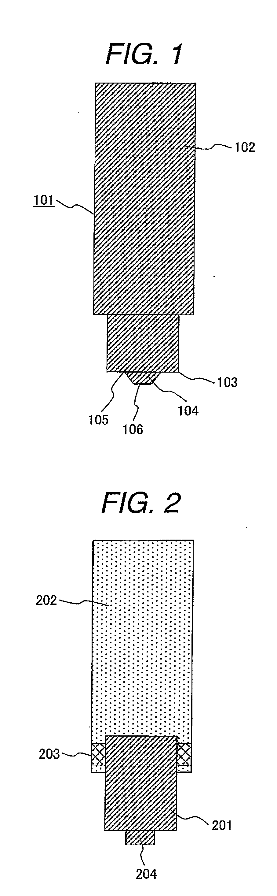
[0028]FIG. 1 shows an embodiment of a friction stir welding tool 101 according to the present invention. A friction stir welding tool 101 according to this embodiment comprising a shank 102 connected to a spindle of the welding apparatus, a shoulder 103 which comes in contact with a surface of a material to be welded while welding is executed, and a pin 104 which is inserted into the material to be welded while welding is executed. The shank 102, shoulder 103 and the pin 104 which are made of Mo alloy having a dual phase microstructure of Mo and Mo5SiB2 are integrated into one unit. Composition of Mo alloy is Mo-8.7Si-17.4B, in which the measuring unit is mol %. As shown in a pattern diagram of FIG. 6, the crystalline structure of Mo alloy is composed of island shaped Mo-phase 601 and Mo5SiB2-phase 602 matrix which is an intermetallic compound.
[0029]Friction stir welding of iron material SS400 was executed by a friction stir welding tool wherein the diameter of its shoulder 103 is 1...
embodiment 2
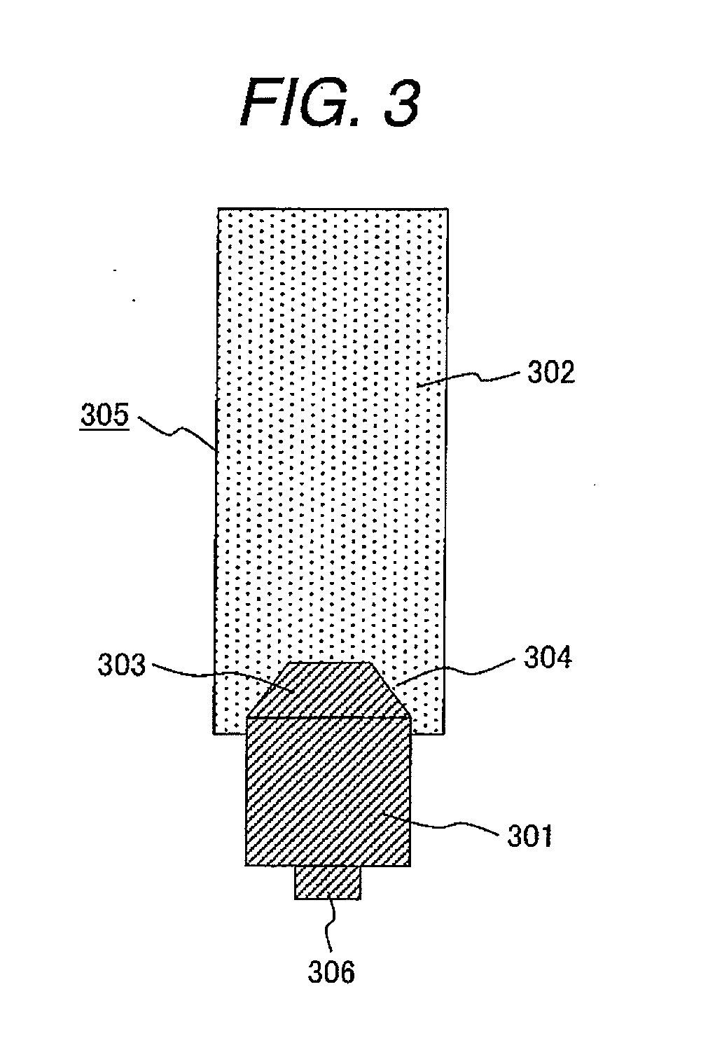
[0045]In this embodiment of the present invention, as shown in FIGS. 2 and 3, a method of making the tool tip of a friction stir welding tool by using Mo alloy, wherein the tool tip is fixed by the shank and the screws or the fixture will be explained.
[0046]FIG. 4 is an explanatory drawing to show a method of making the tool tip by the arc melting method. Mo material 402, Si material 403 and B material 404 are put in a melting furnace 401, and those materials are melted by an arc 405. Molten materials are mixed in the melting furnace 401. Mixed molten material 406 is then poured into a plurality of molds 407 in the shape of the tool tip. According to that work flow process, the tool tip is made. It is desirable that the molds 407 be heated to a temperature higher than the melting point of the molten material 406. By doing so, right after the molten material 406 has been put into the mold 407, the material is quickly solidified, and preventing the occurrence of defects including poro...
embodiment 3
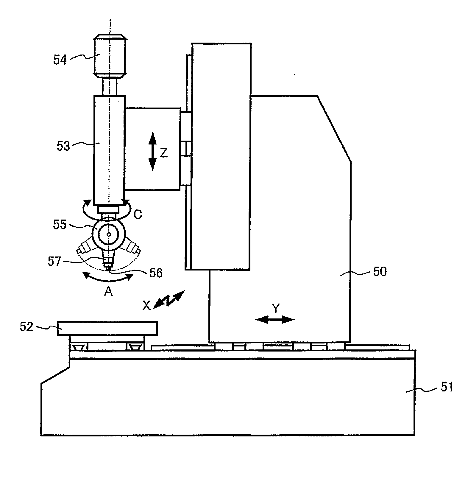
[0048]FIG. 7 shows an embodiment of a friction stir welding apparatus equipped with a friction stir welding tool according to the present invention. This welding apparatus is a three-dimensional welding apparatus which incorporates a correction mechanism for correcting the relative distance between the tool and the material to be welded and is also a column-type apparatus made by modifying a column-type five-axis machining center. This welding apparatus has 5 axes: orthogonal 3 axes (X,Y,Z), rotational C axis around the Z axis, and A axis which is the wrist part of the tool tip. Because the tool is forcibly inserted into a material to be welded during friction stir welding, the welding apparatus must have high rigidity to withstand the reaction force to this insertion. Although the welding load is determined by many factors, such as the material to be welded, plate thickness, tool shape, rotation speed of tool, and welding speed, the load becomes higher as the plate thickness increa...
PUM
| Property | Measurement | Unit |
|---|---|---|
| Fraction | aaaaa | aaaaa |
| Microstructure | aaaaa | aaaaa |
Abstract
Description
Claims
Application Information