Heating tank and hot water storage tank

a technology for hot water storage tanks and heating tanks, which is applied in the direction of heating types, lighting and heating apparatuses, instruments, etc., can solve the problems of increased device cost and power consumption, polluted hot water storage tanks, and increased heat loss, so as to achieve efficient heating and produce hot water more efficiently

Inactive Publication Date: 2008-06-05
SANYO ELECTRIC CO LTD
View PDF22 Cites 22 Cited by
  • Summary
  • Abstract
  • Description
  • Claims
  • Application Information

AI Technical Summary

Benefits of technology

[0024]In addition, according to the hot water storage tank of the sixth invention, the fifth invention includes the cylindrical tank main body, and the heat exchanger has the cylindrical shape, and is arranged concentrically with the tank main body, so that the water in the whole hot water storage tank can efficiently be heated. In consequence, the hot water can highly efficiently be produced.
[0025]Especially, when the insulating material is provided at the inner side surface of the heat exchanger as in the seventh invention, a space where the heat exchanger outside the insulating material is present can be separated as a hot water production area from a cold water area on an inner side of the insulating material. In consequence, cold water supplied from a lower part of the hot water storage tank can be heated in the hot water production area to produce high-temperature hot water, and the produced high-temperature hot water can effectively be stored in an upper part of the hot water storage tank.
[0026]Furthermore, in the sixth or seventh invention, when the plurality of heat exchangers are concentrically arranged as in the eighth invention, the hot water can more efficiently be produced, and the produced high-temperature hot water can be stored in the upper part of the hot water storage tank. In consequence, without impairing production phases of the hot water and the cold water, the hot water can be produced and stored.

Problems solved by technology

However, in a case where the hot water produced via the heat exchanger is stored in the hot water storage tank in this manner, a pump for feeding water is required for circulating the water through the heat exchanger, and there has occurred a problem that a device cost and a power consumption increase.
Furthermore, since the high-temperature hot water produced by the heat exchanger returns to the hot water storage tank via the pipe, reliability of a component such as the pipe needs to be sufficiently considered, and there are many problems that the temperature of the hot water drops in a process of passing the hot water through the pipe, to result in heat loss and the like.
When the pipe is cracked or broken, the water in the hot water storage tank is polluted, and there have been many problems of safety and reliability.
On the other hand, as in the latter case, when the refrigerant pipe of the heat exchanger is wound around the wall surface of the hot water storage tank, heat of the refrigerant is conducted to the water in the tank via the pipe and the wall surface, and this lowers heat conductivity.
Moreover, since a contact area between the pipe and the wall is very small, an even thermally conductive surface cannot be secured, and efficiency deteriorates.

Method used


Image

  • Heating tank and hot water storage tank
  • Heating tank and hot water storage tank
  • Heating tank and hot water storage tank

Examples


embodiment 1

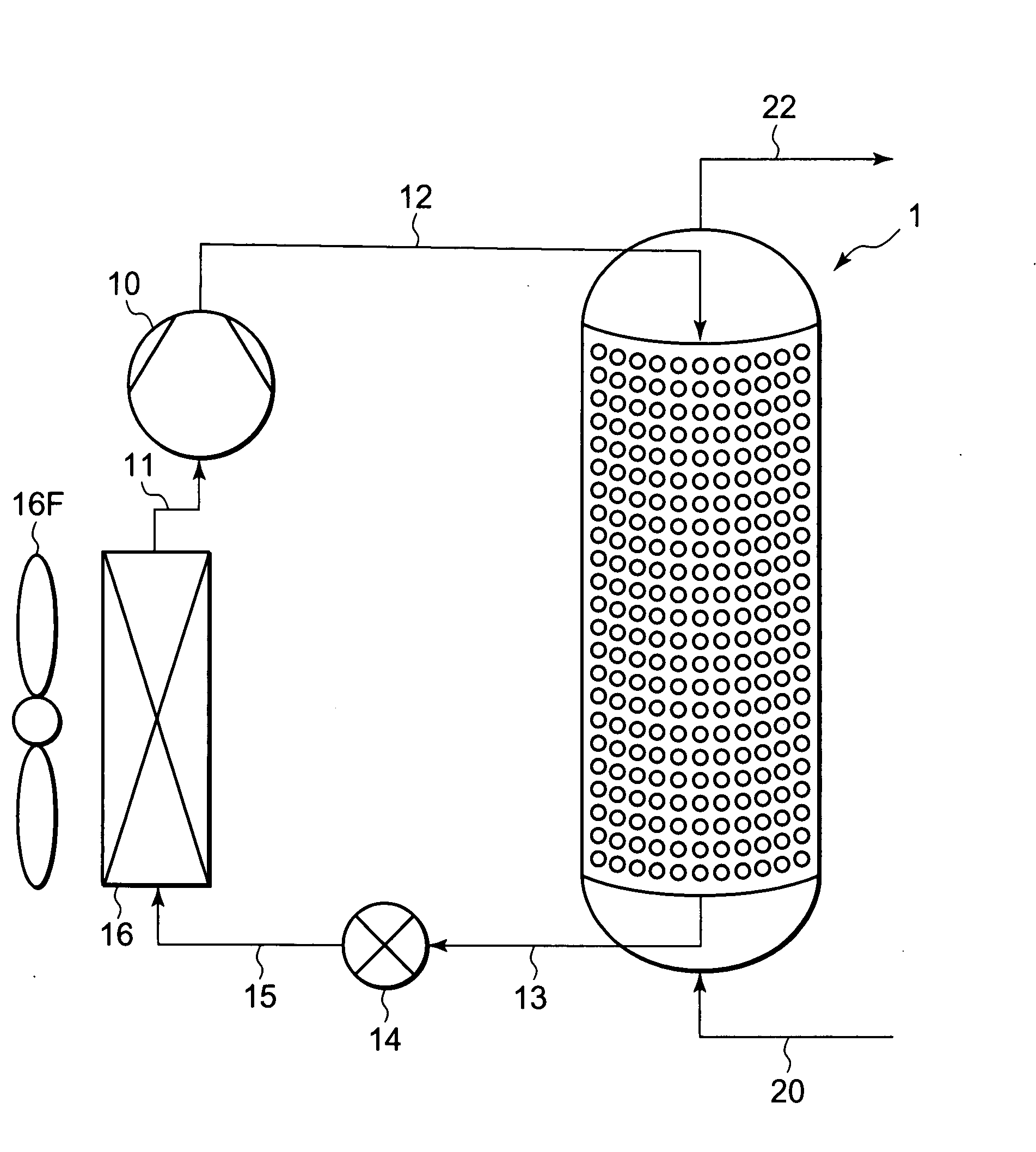
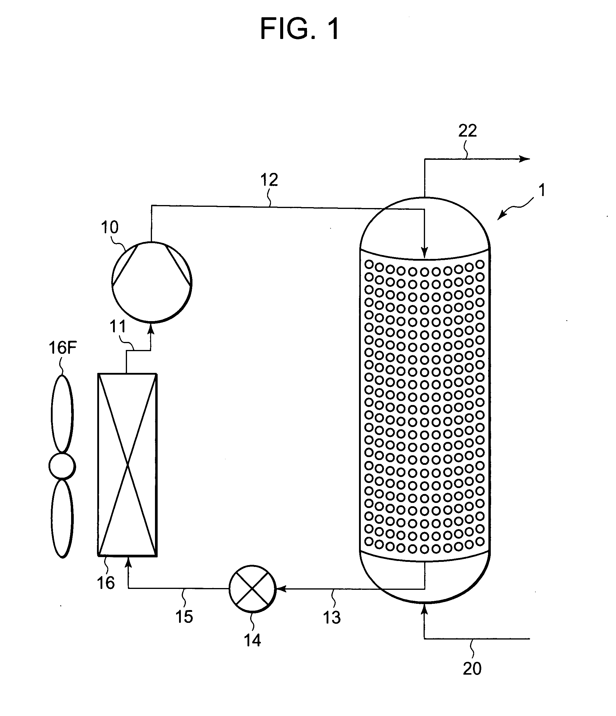
[0044]First, one embodiment in a case where a heating tank of the present invention is applied to a hot water storage tank will be described. FIG. 1 is a refrigerant circuit diagram of a heat pump device including the hot water storage tank according to the present embodiment. A hot water storage tank 1 of the embodiment is a hot water storing tank of a hot water supply device having a function of a heat exchanger which releases heat of a circulated refrigerant of a heat pump. The tank constitutes a refrigerant circuit together with a compressor 10, an expansion valve (a pressure reduction unit) 14 and an evaporator 16.

[0045]That is, a refrigerant discharge tube 12 of the compressor 10 is connected to a refrigerant passage inlet 5 (not shown in FIG. 1) of the hot water storage tank 1, and a refrigerant pipe 13 connected to a refrigerant passage outlet 6 (not shown in FIG. 1) of the hot water storage tank 1 is connected to the expansion valve 14. Then, a refrigerant pipe 15 connected...

embodiment 2

[0078]In Embodiment 1 described above, a tank main body 2 of a hot water storage tank 1 is a heat exchanger, but as shown in FIG. 10, the heat exchanger may be provided in the hot water storage tank 1. FIG. 10 shows a side view of the hot water storage tank 1 in a case where a cylindrical heat exchanger 30 is installed in the hot water storage tank 1. For the sake of description, in FIG. 1, the hot water storage tank 1 is shown in a sectional view, and the heat exchanger 30 and a partition plate 8 are shown in a side view. It is to be noted that in FIG. 10, components denoted with the same reference numerals as those of FIGS. 1 to 9 produce the same effects or similar effects, and description thereof is omitted. In this case, in the heat exchanger 30, shape, since structure and forming method of a tank main body are substantially the same as those of the tank main body 2 of Embodiment 1 described above, here specific description is omitted.

[0079]Since the heat exchanger 30 of the em...

embodiment 3

[0084]Next, another embodiment of the heating tank of the present invention will be described. In the above embodiments (Embodiments 1 and 2), a case where the heating tank is used as a hot water storage tank has been described, but the heating tank of the present invention is not limited to the hot water storage tank which produces hot water, and the heating tank may be used as a tank for fermentation and brewing of foods such as rice malt and soybean paste, a tank for drying and condensing the food, a treatment tank for treating raw garbage, a tank for drying a solvent or water or the like.

[0085]Here, as one example of the above tank, for example, a case where the heating tank of the present invention is used as the treatment tank for drying or condensing the food, or treating the raw garbage or the like will be described in detail with reference to FIGS. 11 to 14. FIG. 11 is a vertically sectional view of a treatment tank 100 according to the present embodiment, FIG. 12 is a sect...


PUM


Abstract

An object is to provide a heating tank capable of highly efficiently heating a target to be heated and having high safety and reliability, and a hot water storage tank. The heating tank in which the target to be heated is stored and which heats the target to be heated by a circulated refrigerant of a heat pump, for example, the hot water storage tank which is heated by the circulated refrigerant of the heat pump to produce hot water in the tank includes a heat exchanger in which a wall surface of a tank main body is partially secured to peripheral edge portions and inner portions of two metal plates and in which non-secured portions swell to constitute a refrigerant passage closed except an inlet and an outlet. A thickness dimension of one metal plate is set to be larger than that of the other metal plate, and the one metal plate is arranged on the inner side of the other metal plate.

Description

BACKGROUND OF THE INVENTION[0001]The present invention relates to a heating tank which heats a target to be heated stored by a circulated refrigerant of a heat pump in the tank, and a hot water storage tank.[0002]Heretofore, in this type of heating tank, for example, a hot water storage tank in which hot water is stored, water (a target to be heated) has been heated by a circulated refrigerant of a heat pump to produce the high-temperature hot water. The hot water is stored in the hot water storage tank, and the hot water stored in the hot water storage tank is taken out, if necessary. Specifically, the hot water storage tank is connected to a heat exchanger via a pipe, and the hot water produced via the heat exchanger is stored in the hot water storage tank.[0003]However, in a case where the hot water produced via the heat exchanger is stored in the hot water storage tank in this manner, a pump for feeding water is required for circulating the water through the heat exchanger, and ...

Claims


Application Information

Patent Timeline
Patent Type & Authority Applications(United States)
IPC IPC(8): F24D11/02
CPCF24H1/208F24H4/04F25B9/008F25B2309/061F25B2339/047F28D1/06F28D20/0034F28F3/12F28F2009/224Y02E60/14F24H7/00
Inventor OTAKE, MASAHISAMUKAIYAMA, HIROSHI
Owner SANYO ELECTRIC CO LTD
Why Eureka
Try Eureka