
Power Supply Device, Light Emitting Device Using Such Power Supply Device, And Electronic Device

a technology of power supply device and power supply circuit, which is applied in the direction of electric variable regulation, process and machine control, instruments, etc., can solve the problems of deteriorating efficiency of the whole circuit and deteriorating of the charge pump circuit, and achieve the effect of high-efficiency operation

Active Publication Date: 2008-06-05
ROHM CO LTD
View PDF2 Cites 47 Cited by
  • Summary
  • Abstract
  • Description
  • Claims
  • Application Information

AI Technical Summary

Benefits of technology

[0013]The present invention has been made in view of these problems, and a general purpose thereof is to provide a power supply apparatus which is capable of higher-efficiency operation by appropriately setting the driving voltage of a load circuit.

Problems solved by technology

Since the efficiency of the charge pump circuit becomes deteriorated according as the boosting ratio becomes higher, the efficiency of the whole circuit will be deteriorated when a margin is set at the threshold voltage for achieving stable operation of the constant current circuit as described above.

Method used


Image

  • Power Supply Device, Light Emitting Device Using Such Power Supply Device, And Electronic Device
  • Power Supply Device, Light Emitting Device Using Such Power Supply Device, And Electronic Device
  • Power Supply Device, Light Emitting Device Using Such Power Supply Device, And Electronic Device

Examples


Embodiment Construction

[0047]The invention will now be described based on preferred embodiments which do not intend to limit the scope of the present invention but exemplify the invention. All of the features and the combinations thereof described in the embodiment are not necessarily essential to the invention.

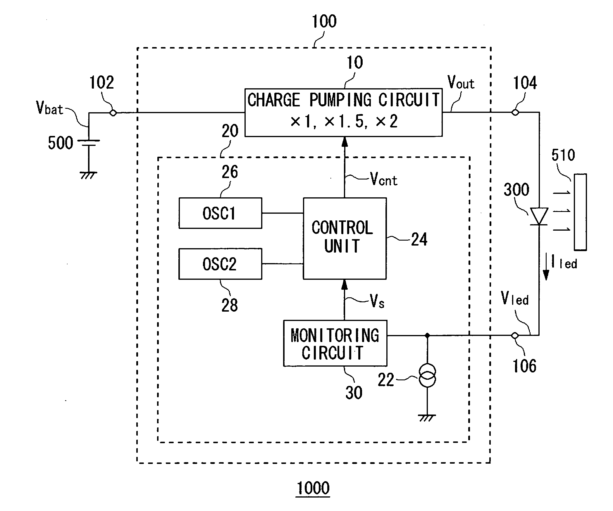
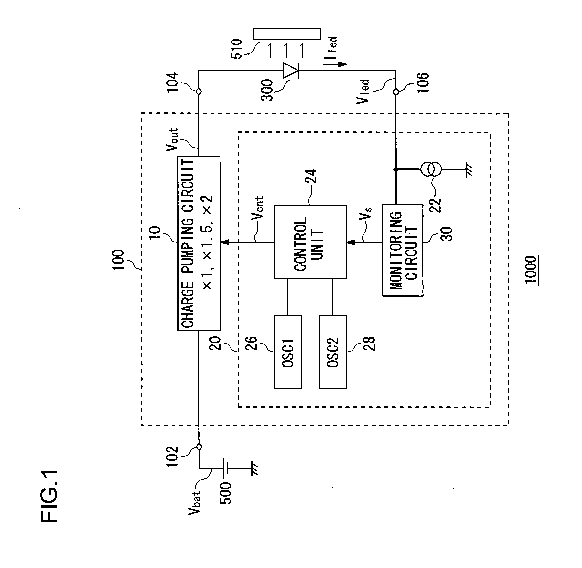
[0048]FIG. 1 shows a light emitting apparatus 1000 according to an embodiment of the present invention. In the subsequent drawings, the same constituent elements will be denoted with the same numerals, and the description will not be repeated appropriately. The light emitting apparatus 1000 is mounted, for example, on an electronic equipment such as a mobile phone terminal or a PDA, and functions as a back light of a liquid crystal. FIG. 1 illustrates a liquid crystal panel 510 together with the light emitting apparatus 1000. A light emitting diode 300 is placed on the back surface of the liquid crystal panel 510, and functions as the back light.

[0049]This light emitting apparatus 1000 includes the...


PUM


Abstract

In a power supply apparatus for performing constant current driving of a light emitting diode which is a load circuit, a constant current circuit is disposed on a path for driving the load circuit. A charge pump circuit which is a voltage generating circuit outputs a driving voltage to the light emitting diode. A monitoring circuit monitors the voltage across the two ends of the constant current circuit. This monitoring circuit includes a voltage source which generates a threshold voltage that follows the fluctuation of the voltage at which the constant current circuit can operate stably, compares the voltage across the two ends of the constant current circuit and the threshold voltage generated by the voltage source, and outputs a comparison result Vs to a control unit. The control unit controls the charge pump circuit on the basis of the output of the monitoring circuit.

Description

BACKGROUND OF THE INVENTION[0001]1. Field of the Invention[0002]The present invention relates to a power supply apparatus.[0003]2. Description of the Related Art[0004]In small information terminals such as a mobile phone and a PDA (Personal Digital Assistance) of recent years, there are devices that require a voltage higher than the output voltage of the battery such as a light emitting diode (hereinafter also referred to as a LED) used as a back light of a liquid crystal, for example. In these small information terminals, a Li ion battery is often used, and the output voltage thereof is typically about 3.5 V, and is about 4.2 V in the fully charged state. However, the LED requires a voltage higher than the battery voltage as the driving voltage thereof. In this manner, when a voltage higher than the battery voltage is required, the battery voltage is boosted with use of a power supply apparatus of booster type using a charge pump circuit or the like, thereby to obtain a voltage nee...

Claims


Application Information

Patent Timeline
Patent Type & Authority Applications(United States)
IPC IPC(8): H05B41/36G05F1/46G05F1/56G05F3/24H01L33/00H02M3/00H02M3/07H05B37/02
CPCH05B33/0815H02M3/07H05B45/38Y02B20/30
Inventor YAMAMOTO, ISAOITO, TOMOYUKI
Owner ROHM CO LTD
Features
  • Generate Ideas
  • Intellectual Property
  • Life Sciences
  • Materials
  • Tech Scout
  • Unparalleled Data Quality
  • Higher Quality Content
  • 60% Fewer Hallucinations
Learn More