Beam-tilted cross-dipole dielectric antenna

a dielectric antenna and cross-dipole technology, applied in the direction of resonant antennas, polarised antenna unit combinations, elongated active element feeds, etc., can solve the problems of antenna performance severely affected, antennas are unable to maintain intrinsic radiation pattern characteristics, and rf signals to degrade to an unacceptable quality, etc., to achieve the effect of reducing signal mitigation or blocking, maintaining acceptable gain, and directionality properties

Inactive Publication Date: 2008-06-05
AGC AUTOMOTIVE AMERICAS
View PDF3 Cites 35 Cited by
  • Summary
  • Abstract
  • Description
  • Claims
  • Application Information

AI Technical Summary

Benefits of technology

[0010]Embedding the beam steering element in the second dielectric layer and electromagnetically coupling the beam steering element to the radiating element allows the antenna to tilt a radiation beam as much as 20 degrees. When mounted on a tilted pane, tilting the beam with the beam steering element reduces signal mitigation or blocking of a signal, and thus, maintains acceptable gain, circul

Problems solved by technology

However, certain parts of the vehicle, such as a roof, may block RF signals and prevent the RF signals from reaching the antenna at certain elevation angles.
Even if the roof does not block the RF signals, the roof may mitigate the RF signals, which may cause the RF signal to degrade to an unacceptable quality.
When this happens, the antenna is unable to receive the RF signals at those elevation angles and the antenna is unable to maintain its intrinsic radiation pattern characteristic.
Thus, antenna performance is severely affected by the roof obstructing reception of the RF signals

Method used


Image

  • Beam-tilted cross-dipole dielectric antenna
  • Beam-tilted cross-dipole dielectric antenna
  • Beam-tilted cross-dipole dielectric antenna

Examples


Embodiment Construction

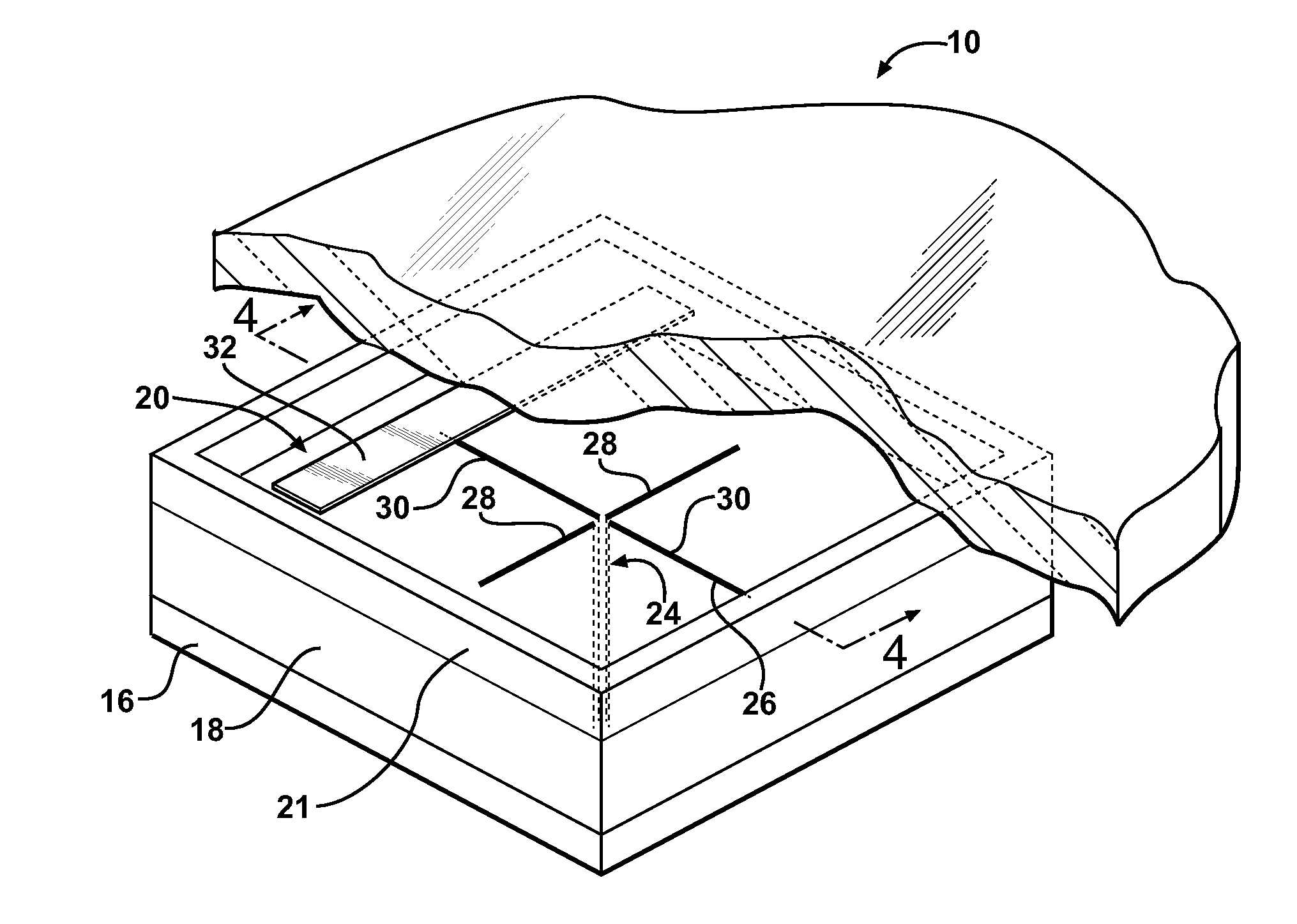
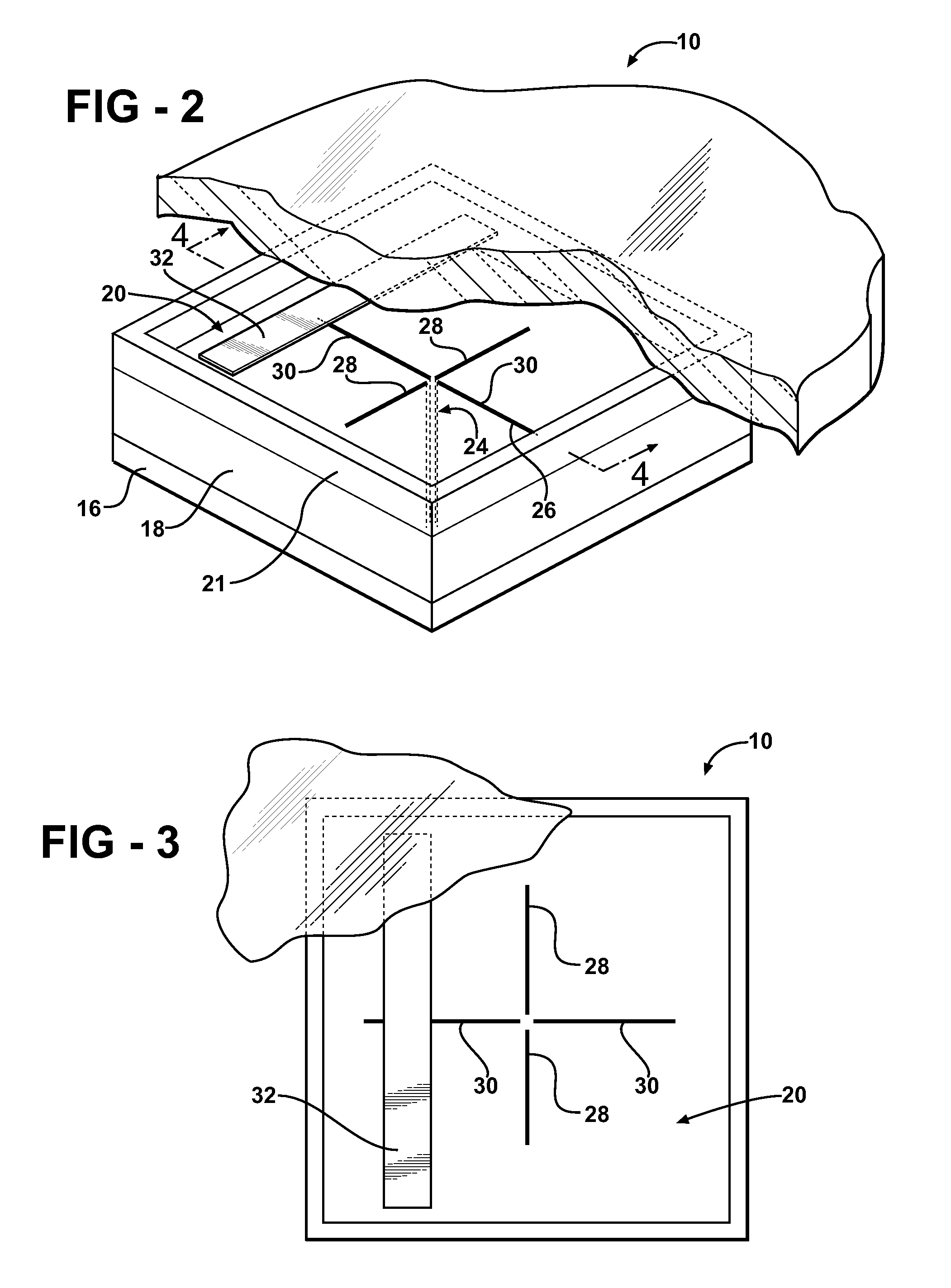
[0019]Referring to the Figures, wherein like numerals indicate corresponding parts throughout the several views, an antenna for radiating an electromagnetic field is shown generally at 10. In the illustrated embodiments, the antenna 10 is utilized to receive a circularly polarized radio frequency (RF) signal from a satellite. Those skilled in the art realize that the antenna 10 may also be used to transmit the circularly polarized RF signal. Specifically, the antenna 10 receives a left-hand circularly polarized (LHCP) RF signal like those produced by a Satellite Digital Audio Radio Service (SDARS) provider, such as XM® Satellite Radio or SIRIUS® Satellite Radio. However, it is to be understood that the antenna 10 may also receive a right-hand circularly polarized (RHCP) RF signal.

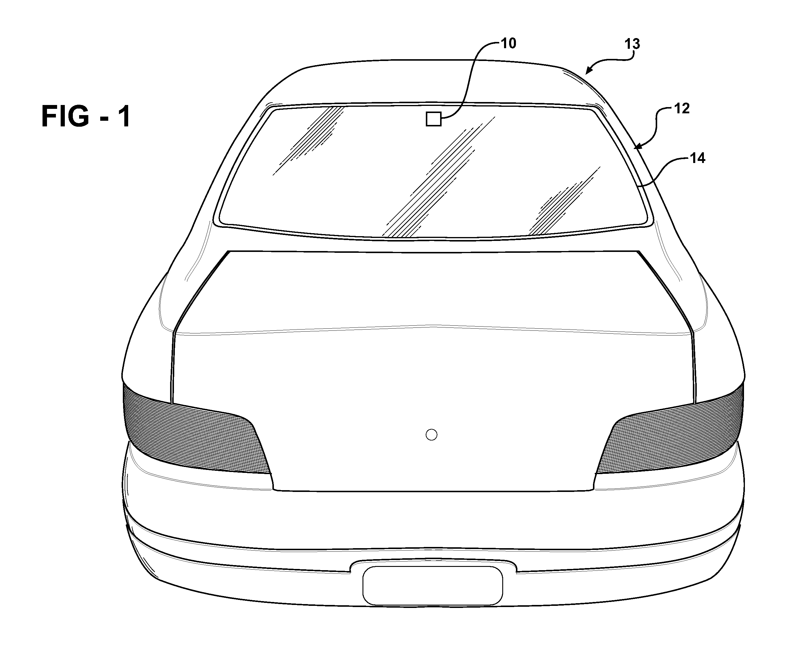
[0020]As shown in FIG. 1, the antenna 10 may be mounted to a window 12 of a vehicle 13. The window 12 may be a rear window 12 (backlite), a front window 12 (windshield), or any other window 12 or tilted pan...


PUM


Abstract

An antenna for radiating an electromagnetic field includes a ground plane, a first dielectric layer disposed on the ground plane, and a second dielectric layer disposed on the first dielectric layer. The antenna includes at least one feeding element embedded in the first dielectric layer and a radiating element extending from the feeding element. The radiating element is embedded within the first dielectric layer adjacent to the second dielectric layer. A beam steering element is embedded in the second dielectric layer and electromagnetically coupled to the radiating element. Embedding the beam steering element in the second dielectric layer and electromagnetically coupling the beam steering element to the radiating element allows the antenna to tilt a radiation beam to overcome a roof obstruction from a vehicle while maintaining acceptable gain, polarization, and directional properties for SDARS applications.

Description

CROSS REFERENCE TO RELATED APPLICATION[0001]This application claims the benefit of provisional patent application Ser. No. 60 / 868,452 filed Dec. 4, 2006.BACKGROUND OF THE INVENTION[0002]1. Field of the Invention[0003]The present invention generally relates to an antenna for radiating electromagnetic waves.[0004]2. Description of the Related Art[0005]Satellite Digital Audio Radio Service (SDARS) providers use satellites to broadcast RF signals, particularly circularly polarized RF signals, back to Earth. SDARS providers use multiple satellites in a geostationary orbit or in an inclined elliptical constellation. The elevation angle between the respective satellite and the antenna is variable depending on the location of the satellite and the location of the antenna. Within the continental United States, this elevation angle may be as low as 20 degrees. Accordingly, specifications of the SDARS providers require a relatively high gain at elevation angles as low as 20 degrees.[0006]The a...

Claims


Application Information

Patent Timeline
IPC IPC(8): H01Q1/32H01Q1/50H01Q21/00
CPCH01Q1/1271H01Q1/32H01Q21/26H01Q1/42H01Q19/22H01Q1/38
Inventor LEE, KWAN-HOVILLARROEL, WLADIMIROSURITTIKUL, NUTTAWIT
Owner AGC AUTOMOTIVE AMERICAS
Why Eureka
Try Eureka