Reinforced masonry sill and threshold sealant backer

Inactive Publication Date: 2008-06-12
PACC SYST I P
View PDF13 Cites 12 Cited by
  • Summary
  • Abstract
  • Description
  • Claims
  • Application Information

AI Technical Summary

Benefits of technology

[0009]Advantageously, this invention permits formation of masonry window sills, door thresholds and the like without direct contact between the frame and the masonry elements, such that the frame is less susceptible to relative contraction and expansion of the inner wall in contact with the frame with respect to the masonry elements. Any expansion or contraction-related upward, downward or lateral movement of the inner wall with respect to the masonry elements is absorbed by a corresponding deformation and / or expansion of selected portions of the structural sponge component of the sealant backer assembly.

Problems solved by technology

Due to the difference in materials between, for example, an inner wood frame wall and an outer masonry wall including bricks, relative contraction and expansion of an inner wooden wall with respect to the window sill or door threshold formed of brick may occur, which may exert pressure on the window or door frame, thereby changing the frame's shape, size and position and potentially damaging or detrimentally affecting the operation and / or appearance of the window or door.
If a brick along the sill or threshold is positioned such that it exerts an excessive force against the window or door frame, it may cause the frame to deform, thereby compromising the stability of the installation or the operation and / or appearance of the window or door.
A challenge during installation of a window sill or door threshold lies in the lack of guidance a mason has when canting the bricks or similar masonry elements downwardly.
It is difficult for the mason to provide a uniform angle for all bricks or other masonry elements along a window sill or door threshold if the installation is such that the inner-wall-facing ends of the bricks cannot touch the horizontal frame member of the window.

Method used


Image

  • Reinforced masonry sill and threshold sealant backer
  • Reinforced masonry sill and threshold sealant backer
  • Reinforced masonry sill and threshold sealant backer

Examples


Embodiment Construction

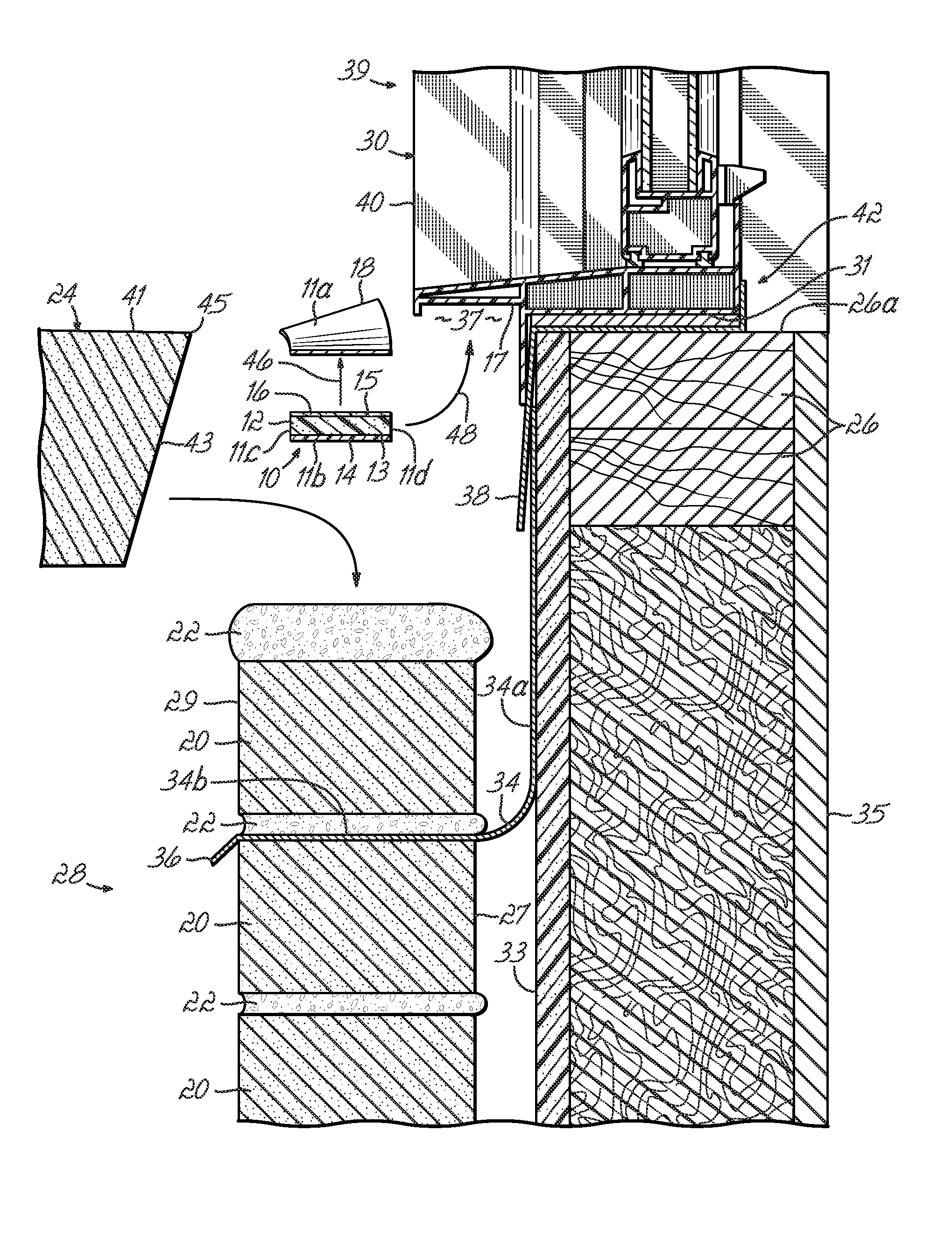
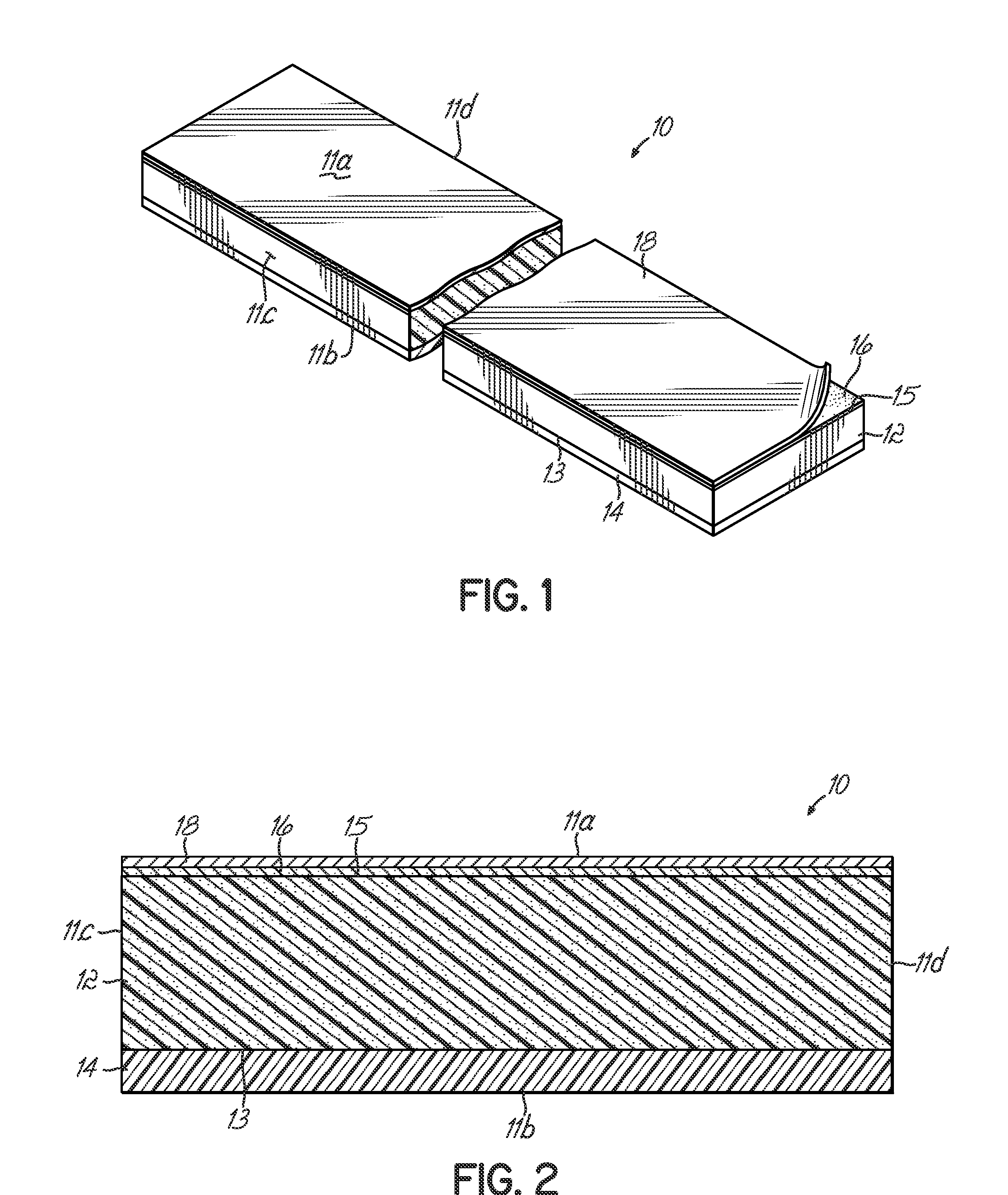
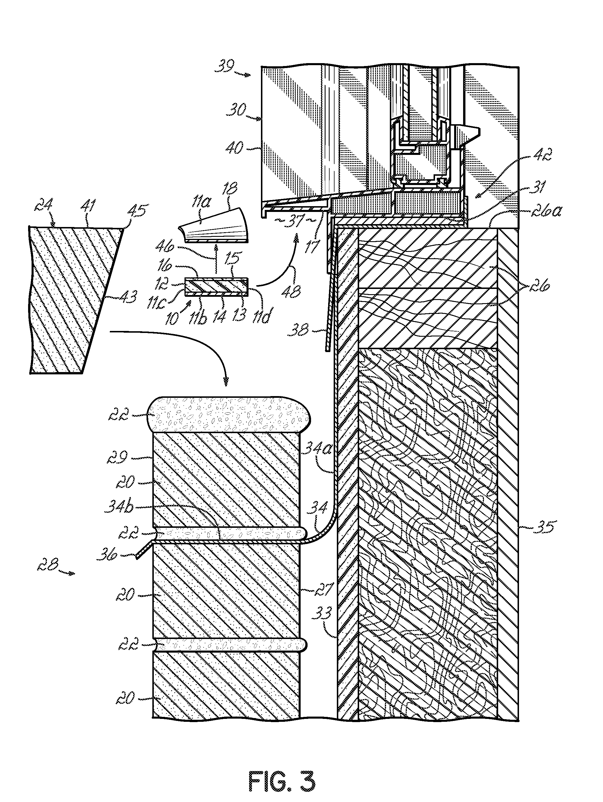
[0022]With reference to FIGS. 1-2, a sealant backer assembly 10 in one embodiment of this invention has a generally rectangular cross-sectional profile and includes a structural sponge component 12 occupying most of the volume defined by the sealant backer assembly 10, a rigid hard backing element 14, an adhesive element in the form of a thin layer 16 and a thin releasable element 18. The sealant backer assembly 10 is further defined by top and bottom faces 11a, 11b and lateral faces 11c, 11d.

[0023]With reference to FIGS. 1-3, the structural sponge component 12 has opposed first and second faces 13, 15 and is made of a suitable material such that the component 12 can withstand a force exerted by an underlying row of masonry elements such as bricks 24. The length and width of the structural sponge component 12 is such that it can fit in a space between a window frame 30 and a row of masonry elements such as bricks 24 or stucco elements 37 (FIG. 7) defining a window sill or door thre...


PUM


Abstract

An apparatus for insertion between a masonry element at least partially defining a perimeter of an opening in an architectural structure and a frame surrounding the perimeter and having at least one surface includes a sponge structure adapted to rest against the frame and having at least one surface. The apparatus further includes a rigid member affixed to the sponge structure and adapted to rest against the masonry element and a coupling element affixed to the sponge structure and adapted to be coupled to a surface of the frame. In another aspect of this embodiment, the surface of the sponge structure is adapted to adhere to a sealant. The sponge structure may include closed cell blended EPDM neoprene.

Description

FIELD OF THE INVENTION[0001]The invention generally relates to the formation of outer walls, window sills and door thresholds. More specifically, the invention relates to devices permanently installed to facilitate the formation of window sills and door thresholds and which provide decreased susceptibility of window and door frames to contraction and expansion of inner walls with respect to outer wall masonry elements in an architectural structure.BACKGROUND OF THE INVENTION[0002]In the field of construction, windows and doors are commonly desirable. A window may include a window frame located in an opening through a wall, which communicates the exterior and interior portions of an architectural structure such as a residence. Similarly, a door may include a door frame communicating the exterior and interior portions of an architectural structure. A wall in a residence or other type of construction may have an inner, wooden frame wall spaced from an outer wall including masonry eleme...

Claims


Application Information

Patent Timeline
IPC IPC(8): E06B1/70E06B1/04E04G21/14
CPCE06B1/62E06B1/702E06B2001/628E06B2001/626E06B2001/624
Inventor COLLINS, P. MICHAEL
Owner PACC SYST I P
Why Eureka
Try Eureka