Heating Fabric and Manufacturing Method Thereof

a technology of heat insulation fabric and manufacturing method, which is applied in the direction of knitting, prosthesis, blood vessels, etc., can solve the problems of increasing the contact resistance at the contact portion between the conductive part and the power line, reducing the reliability of products, and reducing the number of after-service demands. , to achieve the effect of reducing product failures, facilitating connection, and enhancing product reliability

Inactive Publication Date: 2008-06-12
PACIFIC MEDICAL
View PDF0 Cites 11 Cited by
  • Summary
  • Abstract
  • Description
  • Claims
  • Application Information

AI Technical Summary

Benefits of technology

[0009]As is apparent from the above descriptions, the heating fabric according to the present invention provides the advantages in that a heating fabric element is easily connected to a heating fiber by a conductive part made by weaving, the reliability of products is enhan

Problems solved by technology

However, the connection method using the double-side press terminal also has the disadvantage of a short circuit, which can easily occur due to the press.
Accordingly, even though the terminal is compressed, the connection is not always successful, so that contact resistance at the contact portion between the conductive part and the power line increases.
As a resul

Method used


Image

  • Heating Fabric and Manufacturing Method Thereof
  • Heating Fabric and Manufacturing Method Thereof
  • Heating Fabric and Manufacturing Method Thereof

Examples


Embodiment Construction

[0017]Hereafter, a heating fabric made by consolidating a fabric which is a heating fabric element, a heating fiber and a power line, according to one embodiment of the present invention, will be described with reference to the accompanying drawings.

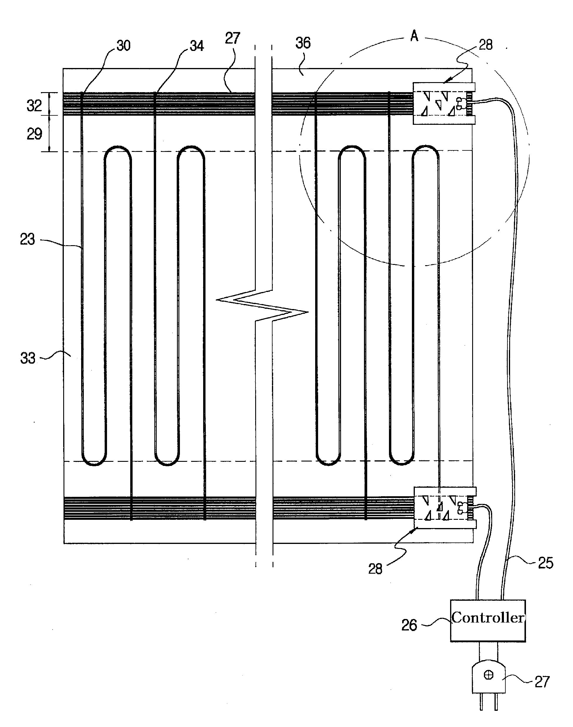
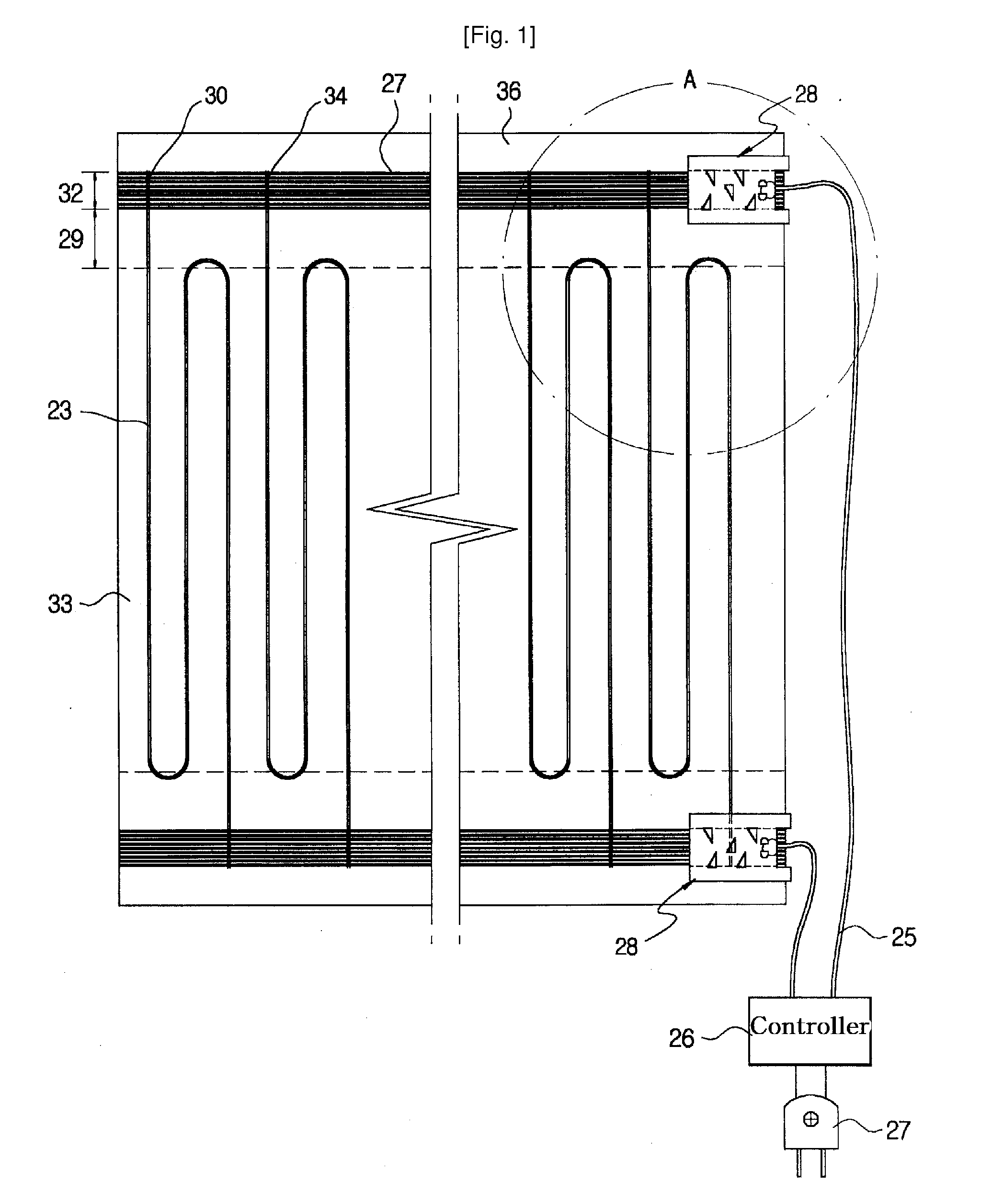
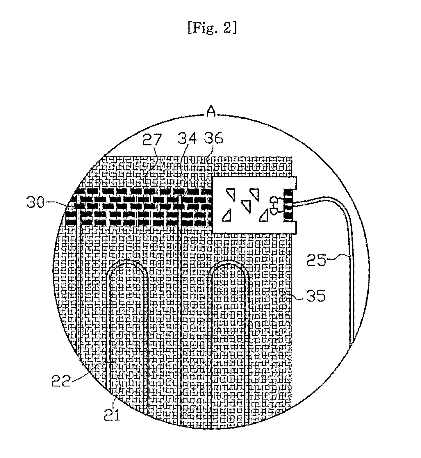
[0018]As shown in FIGS. 4 to 9, a heating fabric according to a first embodiment of the present invention comprises a heating fabric element 33 which is made by weaving woof threads 22 and warp threads 21, which are made of fibers 35. The fiber used in the heating fabric element 33 is a natural fiber of 4 / 20, polyester filament or glass yarn.

[0019]The heating fabric 20 according to the present invention is made by weaving a heating fiber 23 and fibers 35 together. In the case of using the heating fiber 23 as the warp thread 21, first the fibers 35 are woven as the warp threads 21 by 10 mm to 15 mm, and then the heating fiber 23 is continuously woven as the warp thread 21 to form a zigzag pattern.

[0020]A pair of conductive parts 32 for su...


PUM

PropertyMeasurementUnit
Electrical resistanceaaaaaaaaaa
Electrical conductoraaaaaaaaaa
Strengthaaaaaaaaaa

Abstract

Disclosed is a heating fabric comprising a heating fabric element made by weaving woof fibers and warp fibers, a pair of conductive parts being a plain fabric made by a weaving method to extend from one side edge of the heating fabric element, for supplying electric power to the heating fabric element, wherein electrode fibers are woven in rows as warp threads in the conductive parts and a heating fiber is intermittently woven as woof threads at predetermined intervals so as to be conductive with the conductive parts, and wherein the heating fiber is woven in a zigzag pattern on the other side of the plain fabric of the conductive parts, in which one end of the heating fiber is woven into the conductive part, and a portion of the other end of the heating fiber is not woven into the conductive part, thereby forming a jumping portion having a length longer than a width of the conductive part, the jumping portion jumping over the conductive part so as not to be conductive with the conductive part. Due to the one-side arrangement of the conductive parts and the zigzag pattern of the carbon fibers, electromagnetic waves are reduced and offset. Accordingly, the heating fabric is advantageous for a user's health.

Description

TECHNICAL FIELD[0001]The present invention relates to a heating fabric and a method of manufacturing the same. More particularly, the present invention relates to a heating fabric having a conductive part provided at a side edge of a heating fabric element made by weaving fibers as woof threads and warp threads for supplying electric power to the heating fabric element, in which the conductive part is made by weaving tin-plated wires as woof threads and regular fibers as warp threads, and a method of manufacturing the heating fabric.BACKGROUND ART[0002]Generally, a film heater is made by two methods. According to one method, a conductive material, such as carbon, having a predetermined resistance, is coated on an insulator in a predetermined pattern, so that the heater generates heat by applying a current to the conductive pattern. According to the other method, an electrically resistive wire, such as carbon wire or nichrome wire, is mixed as woof threads or warp threads when weavin...

Claims


Application Information

Patent Timeline
IPC IPC(8): D03D15/00H05B3/20D03D23/00
CPCH05B3/12H05B3/145H05B3/347H05B2203/017H05B2203/005H05B2203/011H05B2203/015H05B2203/004Y10T442/2475Y10T442/3065Y10T442/3146Y10T442/3179Y10T442/3301Y10T442/3317Y10T442/3382Y10T442/339Y10T442/3854Y10T442/3976
Inventor SEO, YOUNG CHEOL
Owner PACIFIC MEDICAL
Why Eureka
Try Eureka